 |
|||
|
Page Title:
Figure 3-32.--Cyro alarm circuits--signal flow. |
|
||
| ||||||||||
|
|
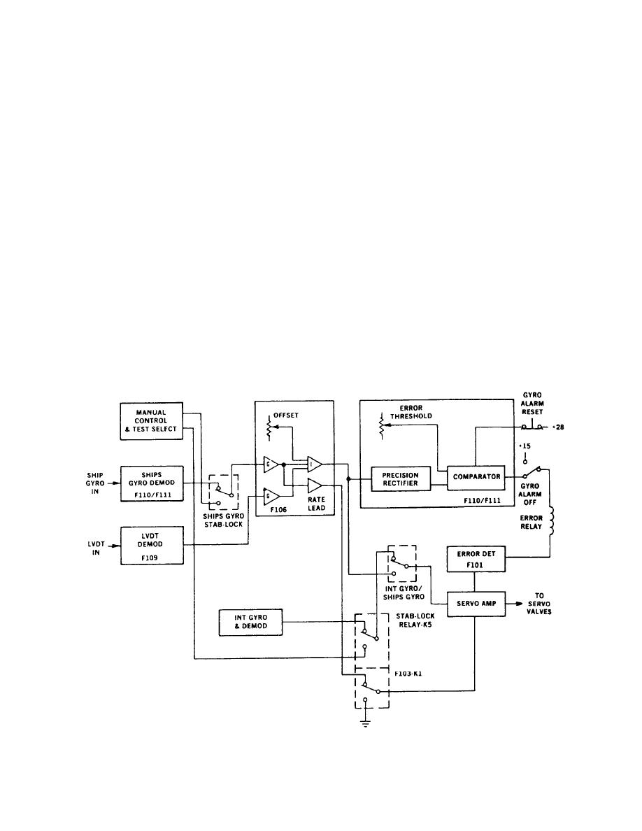 The gyro alarm failure alarm circuit can be disabled
A simplified signal flow diagram of the gyro alarm
by pushing the gyro alarm OFF push button. This
circuits is shown in figure 3-32. The switches are shown
supplies +15 volts dc to one side of the error relay and
in the normal mode of operation; namely, internal gyro
effectively disconnects the gyro failure alarm circuits.
operation with the failure alarm armed The gyro alarm
In addition an interlock circuit prevents unwanted plat-
circuit is only tied to the system in this mode by the
form oscillation when the alarm circuit is not actuated.
system supplies and the error relay. In operation, the ship
gyro signal is converted to a dc signal in the linear
Gyro Demodulator Board
synchro to dc converter (F110/F111). This signal goes
through the ship gyro stab-lock switch, is amplified in
the F106 card and is summed with a scaled voltage from
The gyro demodulator board contains a synchro to
dc converter and a gyro error detector circuit. The F110
the platform LVDTs and an offset voltage that makes up
and F111 are identical cards: one is used in the pitch
for alignment differences between the ship gyro and the
channel and the other in roll. The synchro to dc converter
platform base. This summed signal (error voltage) is
is a sealed module not repairable by shipboard person-
applied to the F110/F111 card, full-wave rectified,
nel.
faltered and compared against a preset threshold. If
the error voltage exceeds the preset threshold, the
Gyro Error Detector Circuit
comparator trips and removes the +15 volts from the
error relay. This turns off the SGSI cell and gives a not
ready indication at the remote panel. The comparators
The gyro error detector circuit consists of a pre-
on the F110/F111 cards are electrically latching relays.
cision N-wave rectifier, a filter, a voltage comparator,
If the error is removed, these relays can be reset by
a transistor, and a relay. The input signal to this card is
pushing the gyro alarm reset button to remove latching
the summation of the ship's gyro and the platform
LVDTs.
voltage.
Figure 3-32.--Cyro alarm circuits--signal flow.
3-24
|
|
Privacy Statement - Press Release - Copyright Information. - Contact Us |
