 |
|||
|
Page Title:
Figure 3-27.--Inverting amplifier diagram. |
|
||
| ||||||||||
|
|
 Servo amplifiers
Dither oscillator
Error circuit
Gyro alarm circuits
Gyro signal card
Source light failure detector
Power distribution circuits
Gyro Demodulator
The gyro demodulator is a nonrepairable item. The
gyro demodulator receives 115-volts ac, 400-Hz
reference signals from stator leads S1 and S3 of the pitch
and roll synchros in the gyro. The demodulator converts
the ac synchro signals to dc with the in-phase ac signal
positive and the out-of-phase signal being negative. This
type of demodulator is called a phase-sensitive rectifier.
For an in-phase signal, the device behaves as a bridge
rectifier with a capacitor falter to remove ripple.
Figure 3-27.--Inverting amplifier diagram.
The internal gyro synchros that feed the demod-
ulator are excited with 26 volts ac, 400 Hz and have a
maximum output between S1 and S3 of 11.8 volts ac at
its input resistor and the feedback resistor with the inputs
90 rotation. When the signals are demodulated by the
added.
gyro demodulator, the output is 10 volts dc at 90 of
No voltage greater than 15 volts should be applied
rotation from horizontal.
to any pin of an op-amp or damage will result. The
op-amps output is short-circuit protected; thus, shorting
Linear Voltage Differential Transformer
the op-amps outputs will not damage them. Op-amps
exhibit three common types of failures: no output,
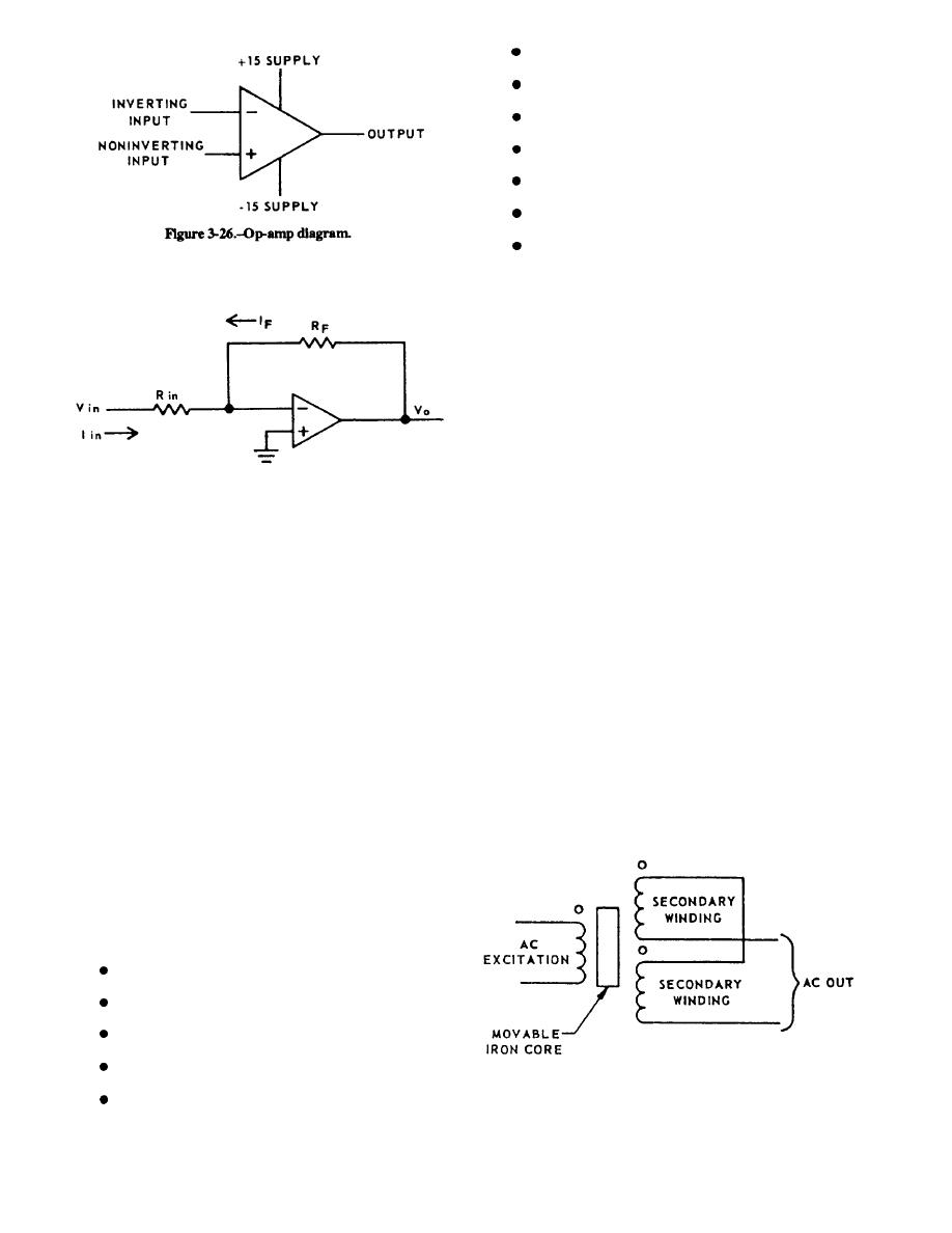
The LVDT is an ac electromechanical transducer
saturated positive, and saturated negative. A saturated
that converts physical motion into an output voltage
voltage is one that is maximum for a particular op-amp
whose amplitude and phase are proportional to position.
usually greater than 11 volts. Any op-amp whose output
In operation, an ac excited primary winding is
is greater than 11 volts and does not change with varying
coupled to two secondary windings by a moveable core
inputs may be defective. Check for large inputs and open
placed between them (fig. 3-28). Displacement of the
feedback resistors before replacing the op-amp.
SYSTEM ELECTRONICS
The GSI system electronics is divided into 13
fictional areas as follows:
Gyro demodulator
LVDT
LVDT demodulator card
LVDT oscillator
Figure 3-28.--LVDT aimplified schematic
LVDT demodulator
3-19
|
|
Privacy Statement - Press Release - Copyright Information. - Contact Us |
