 |
|||
|
|
|||
| ||||||||||
|
|
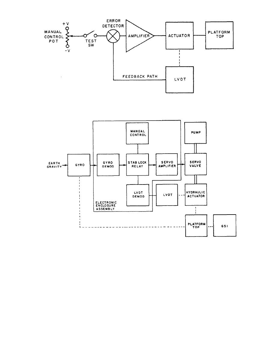 Figure 3-23.--LYDT servo loop.
Figure 3-24.--Stabilization circuits, block diagram.
The LVDT loop is quite similar to the gyro feedback
are only generated when the LVDT has an output and
loop, only the sensor is changed Figure 3-23 shows that
these are amplified and drive the output to zero.
the LVDT is mechanically connected to the actuator to
In operation, any voltages measured in the servo
sense its position pot. The feedback signal from the
loops are small and are proportional to the system
LVDT is connected to the error detector. The LVDT has
error.
as its input either zero (stab-lock) or a signal from the
The complete system servo feedback loop (single
manual position pot. With the manual position pot
channel) is shown in figure 3-24. This incorporates both
switched out of the circuit, the input to the error detector
the gyro and stab-lock loops and the switching between
is zero (ground). The LVDT is adjusted so its output is
them.
zero when the platform top is level to its base, thus errors
3-17
|
|
Privacy Statement - Press Release - Copyright Information. - Contact Us |
