 |
|||
|
Page Title:
Figure 3-17.--Gulide slope indicator, simplified functional diagram. |
|
||
| ||||||||||
|
|
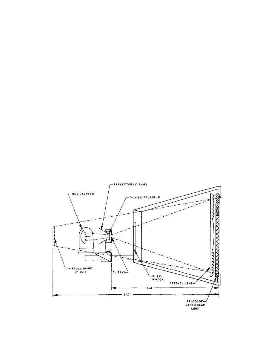 At the same time the cell is focused it can
Thus, the cell can be focused and the sensitivity set
be calibrated for proper glide slope. Referring to fig-
by moving the light source and slots in relation to the
colored filter (fig. 3-17). In the GSI cell, the distance
ure 3-19, you can see that the same screen arrangement
from the slots to the Fresenel lens is 16.8 inches. The
can be used for measuring the angle of the red/amber
cell is calibrated so the 1-inch amber section of the
inter- face.
lenticular lens is exactly 1 degree of arc. A typical cell
Set the baroscope supplied with the system on top
calibration setup is shown in figure 3-18.
of the level plate and mark off a reference mark on each
To focus the cell, it must be placed on a level plate
screen. Adjust the cell glide angle using the knurled
and two screens 10 feet (1/8 inch) apart must be set up
knob under the lamp housing until the difference be-
in front of the cell (see fig. 3-18). Turn the cell on and
tween the reference mark on the red/amber interface on
measure the height of the amber at screen one and
screen two is equal to 6-9/32 inches 7/32 inch. Drill
subtract it from the height of the amber at screen two
and pin the degree plate so it indicates three degrees.
(fig. 3-19). If the cell is properly focused, the difference
should be 2-3/32inch1/8 inch. A dark band will appear
In this measurement, the cell should project the
between each of the colors due to light scattering at the
beam on the two screens and the center of the dark band
interface; this band should be split evenly to obtain
between the red and amber filter should be used for all
height measurements.
measurements.
The slot through which the light bar is formed
Beam Angle
determines the size of the light bar as it is viewed
through the cell face. In this system, it is not adjustable.
The angle of the light beam to the horizon must be
accurate and remain constant so a pilot may maintain a
THERMAL CONTROL
fixed rate to the ship. The glide slope angle is set using
the degree plate on the right side of the cell and is
Temperature control of the GSI includes cooling
checked on-the platform by means of pole checks to
of the projection lamp compartment and temperature
ensure the proper settings.
Figure 3-17.--Gulide slope indicator, simplified functional diagram.
3-12
|
|
Privacy Statement - Press Release - Copyright Information. - Contact Us |
