 |
|||
|
Page Title:
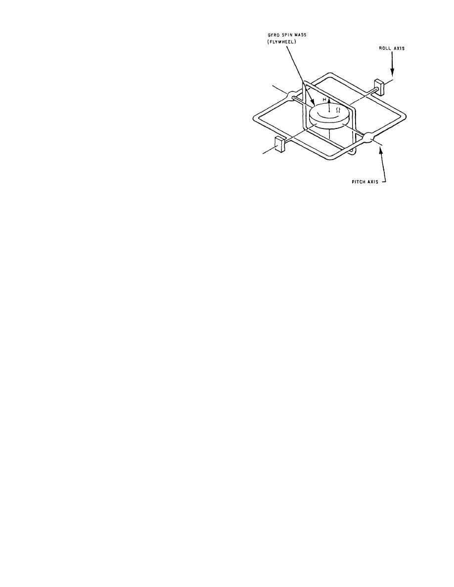
Figure 3-14.--Vertical gyro, simplified schematic. |
|
||
| ||||||||||
|
|
 you can locate the cause of the specific malfunction and
perform the recommended corrective maintenance.
Maintenance is an ongoing process to keep the
equipment operating effciently and consists of pre-
ventive and corrective maintenance. For all main-
tenance requirements for the SGSI system, you should
refer to the maintenance requirement cards (MRCs).
There are maintenance items to be performed weekly,
quarterly, semiannually, and annually. System main-
tenance must be performed on a regular basis regardless
of use cycle. Deterioration and/or damage to equipment
may result if system maintenance is not performed
regularly. The information given in the following para-
graphs is not intended to replace preventive main-
tenance cards or the applicable technical manuals. This
information should familiarize you with some of the
requirements and procedures to keep the equipment in
Figure 3-14.--Vertical gyro, simplified schematic.
top notch operating condition.
GYRO ALARM OFF
When the flywheel of the gyroscope is rotating at
high speed, its inertia is greatly increased. This causes
If a failure occurs in the error sensing circuitry or if
the flywheel to remain stationary within the gyro gimbal
the ship's gyro information or gyro reference voltage is
structure. To align the gyroscope flywheel to the local
not being sent to the SGSI, a ready light cannot be
earth gravity vector (downward pull of gravity), a
obtained. This will keep the lamp relay de-energized and
pendulum sensor is attached under the spinning fly-
not allow the source lamps to illuminate. Operation in
wheel. In operation, the pendulum is held suspended
the internal gyro mode is still possible through the
within a magnetic sensor with the magnetic sensor
activation of the gyro alarm off switch-indicator on the
measuring the difference between the pendulum axis
component panel assembly. Since the gyro alarm off
and the spin motor axis. The sensor output is amplified
switch-indicator disables the independent failure detec-
tion circuit, a gyro alarm off indicator is automatically
flywheel to rotate in a direction to reduce the sensor
illuminated in both the electronic enclosure and the
output. In actual operation, the pendulum sensor is
remote control panel. Servo error sensing is not affected
affected by lateral accelerations that cause it to oscillate
by activation of gyro alarm off. Depressing the gyro
about true position. To correct for this oscillation, the
alarm off push button will activate the ready light and
gyro circuits time constants are long. The long time
allow the source lamps to illuminate if no other system
constants cause the gyros flywheel to ignore periodic
problems exist.
variations of the pendulum and align itself to the average
pendulum position. Figure 3-15 shows the essential
GYRO FAILURE ALARM CIRCUIT TESTS
elements of the gyro.
These tests are to be performed once a week when
CELL ALIGNMENT
the SGSI is being used for air operations. These tests
will ensure that all failure monitoring circuits are
For a pilot to use the SGSI for an accurate landing,
operational.
the cell must be properly aligned. There are two adjust-
ments necessary for this alignment. One adjustment is
VERTICAL GYROSCOPE
focusing the cell and the other is setting the beam angle
in reference to the GSI base plate.
The vertical gyroscope is basically a mechanical
device. The essential element of the gyroscope is a
Cell Focusing
flywheel rotating at high angular velocity about an axis.
The flywheel is mounted within gimbals that allow it
As shown in the simplified cell schematic, fig-
ure 3-16, you can see that by moving the light mask into
two degrees of freedom as shown in figure 3-14.
3-10
|
|
Privacy Statement - Press Release - Copyright Information. - Contact Us |
