 |
|||
|
Page Title:
Figure 3-7.--Stabilization control circuitsignal flow. |
|
||
| ||||||||||
|
|
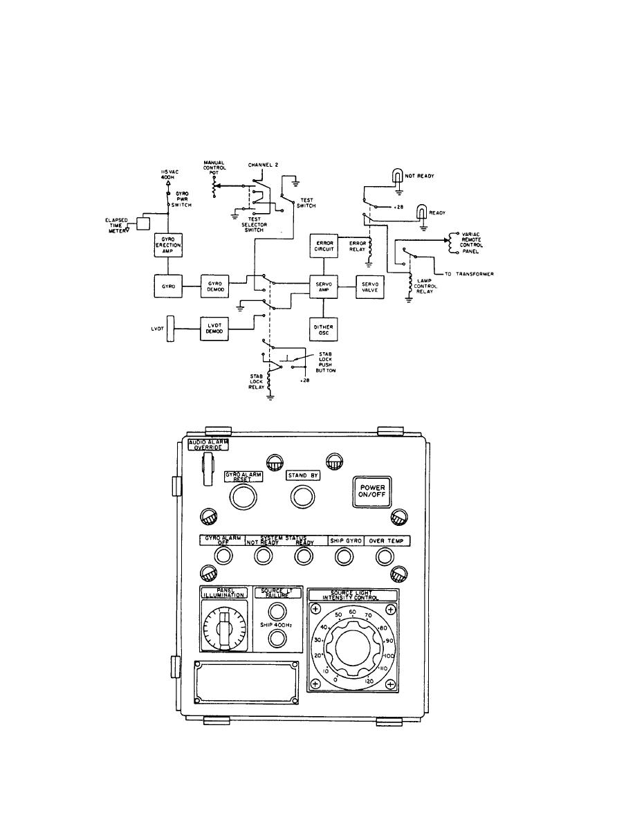 fig. 3-7). When the stab-lock button is pushed, the error
maintenance and alignment of the system. Revisions
signal comes from the linear voltage differential trans-
are also made to drive the platform manually using the
test switches and the manual drive potentiometer.
former (LVDT) when the test switch is in the off
position. The core of the LVDT is mechanically attached
to the hydraulic actuator, which levels the platform. As
REMOTE CONTROL PANEL ASSEMBLY
the actuator moves, the core also moves, thereby
supplying a signal proportional to the amount of roll or
The remote control panel (fig. 3-8) is located in the
pitch. These signals can be measured to aid in the
flight operations control room. TM panel provides
Figure 3-7.--Stabilization control circuitsignal flow.
Figure 3-8.--Remote control assembly.
3-5
|
|
Privacy Statement - Press Release - Copyright Information. - Contact Us |
