 |
|||
|
Page Title:
Figure 2-13.--Computer system, functional diagram. |
|
||
| ||||||||||
|
|
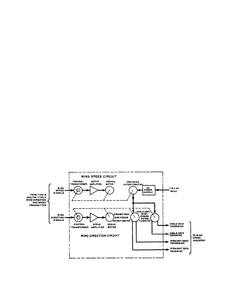 corresponding voltage that is proportional to the speed
CROSSWIND AND HEADWIND
of the wind. This windspeed voltage is then applied to
COMPUTER
the wind direction circuit where the crosswind and
An elaborate development of a transmission system
headwind components are developed.
is the crosswind and headwind computer system, de-
The windspeed synchro signal input is applied to the
signed for use aboard CVAs. Although this system is
not at present intended for use aboard other vessels, its
stator of the control transformer in the windsped
design should be interesting to you as an application of
circuit. The output of the control transformer is an error
voltage representing the difference between the
synchro and servomechanism basics.
electrical angle of the synchro signal and the mechanical
The crosswind and headwind computer receives
angle of the stator in the control transformer. This error
relative wind direction and speed information from a
voltage feeds to the servo amplifier through a
wind direction and speed indicator system, as shown in
transformer, not shown in the functional diagram. The
figure 2-13. The output from the computer is in the form
purpose of the transformer is to compensate for the
of variable voltages. These voltages represent the
phase shift caused by the inductance of the windings of
factors of windspeed from dead ahead, across the beam,
the control transformer rotor. The signal fed to the
and parallel to and across the angled deck of the carrier.
amplifier is either 0 or 180 from correspondence with
These voltages are applied to indicators that provide
the line voltage. The amplifier is a push-pull type, and
direct reading of crosswind and headwind speeds in
applies an output voltage to the second coil of the
knots. The crosswind and headwind computer assembly
servomotor, thereby controlling the direction and speed
is shown in figure 2-14, and a functional diagram of the
of the motor.
computer assembly is shown in figure 2-13. In fig-
ure 2-13, the heavy lines represent signal flow and the
The servomotor drives a gear train that positions the
dashed lines represent mechanical linkages that make
rotor of the control transformer, driving it until it
the system self-synchronous.
corresponds with the input signal. The gear train also
positions the arm of the precision potentiometer that
WINDSPEED CIRCUIT
regulates the dc power supply input. The position of the
arm of the potentiometer determines the amount of
voltage applied to the sine-cosine potentiometer in the
The windspeed circuit takes the synchro signal
wind direction circuit. This voltage is proportional to the
from the windspeed transmitter and converts it to a
Figure 2-13.--Computer system, functional diagram.
2-14
|
|
Privacy Statement - Press Release - Copyright Information. - Contact Us |
