 |
|||
|
Page Title:
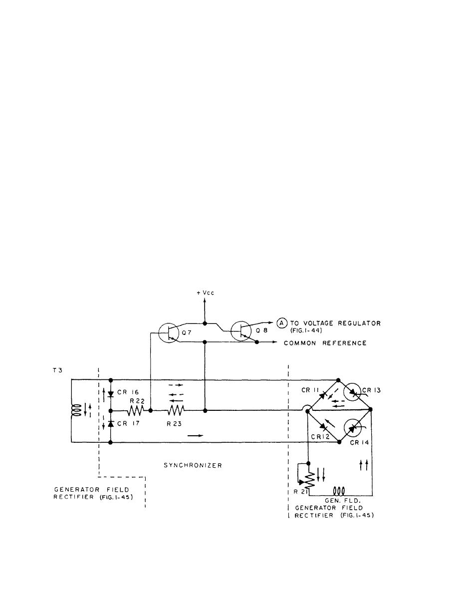
Figure 1-47.--Synchronizer, simplified schematic. |
|
||
| ||||||||||
|
|
 When the alternate bridge rectifier conducts, the
the pulse turns it on. By controlling the phase of the gate
voltage across R23 permits C4 (fig. 1-44) to charge,
pulse (with respect to the supply voltage), the firing
introducing the phase delay of the SCR gate pulse.
(delay) angle of the SCR gate may be delayed to any
Firing of SCRs, CR13, and CR14 applies equal potential
point in the cycle up to approximately 180. Through
at both ends of voltage divider R22 and R23. This
control of the firing angle, the average power delivered
removes the voltage drop across R23 and thus allows
to the load can be adjusted.
Q7 to turn off and Q8 to turn on. Thus, the timing
Referring to figure 1-46, you can see that by apply-
capacitor C4 is clamped until the start of the next half
ing a gate pulse at 0 of the phase time axis (view A),
cycle.
output power will be applied during the complete half
cycle. View B shows that power is obtained for a half of
FREQUENCY DISCRIMINATOR
each half cycle by applying a pulse at 90 of the phase
time axis. The other extreme of no output when the
The speed/frequency regulator automatically main-
phase delay is 180 is represented in view C.
preset value despite line variations or load changes.
SYNCHRONIZER
Constant output frequency is obtained by auto
The function of the synchronizer is to assure that the
matically adjusting the power to the motor control field
firing angle is always reckoned from the instant the
in response to a frequency discriminator. The frequency
supply voltage crosses the zero axis at each positive half
discriminator converts the generator output frequency
cycle (fig. 1-46, view A). As shown in figure 1-47, when
to a voltage signal that is in direct proportion to the
the SCRs are not conducting, an alternate bridge
speed/frequency of the motor generator.
rectifier circuit is. This alternate bridge consists of diode
CR12, resistor R21, the generator field, resistors R23
The speed/frequency regulator circuit is the same as
and R22, diode CR16, and the secondary of T3. During
the voltage regulator previously discussed. The
the alternate half cycle, the patch (dashed arrows) is the
operational difference is that the voltage regulator
required an increase in generator output voltage to cause
same except diodes CR 11 and CR 17 are used.
Figure 1-47.--Synchronizer, simplified schematic.
1-43
|
|
Privacy Statement - Press Release - Copyright Information. - Contact Us |
