 |
|||
|
Page Title:
Figure 1-28.-Zener reference bridge. |
|
||
| ||||||||||
|
|
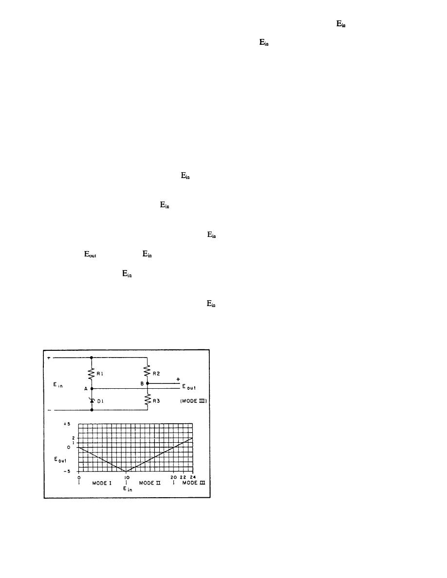 Consider the input voltage
to be 22 volts; then
voltage output that varies linearly with changes in
the output voltage will be 1 volt. Next, consider the input
generator output frequency rather than generator output
voltage
to be 24 volts; then the output voltage will
voltage. The signal voltage obtained from the
be 2 volts. Although the input voltage is 22 volts to 24
frequency-sensing transformer is rectified, filtered, and
volts, the output voltage is only 1 volt to 2 volts. There-
compared in a Zener reference voltage divider, all
fore, without adding additional components to lower the
contained within the detector circuit. This circuit
voltage to the point where it can be used as abase drive
provides an interesting application of Zener diodes, as
for a transistor, the output voltage of the bridge can be
shown in figure 1-28. The purpose of the Zener
used as abase drive for a transistor.
reference bridge is to compare a high-supply voltage
with a reference voltage and to provide a low-voltage
The signal leaving the Zener bridge is amplified by
two dc transistor amplifiers, in the detector, before going
amplitude output signal voltage to be used as a base
to the preamp and trigger (fig. 1-27).
drive for a transistor.
The purpose of the preamp and trigger is to amplify
The Zener reference bridge consists of resistors R1,
and convert the varying dc input voltage into controlled
R2, R3, and Zener diode D1, as shown in figure 1-28.
pulses of sufficient amplitude to fire the SCRs.
Resistors R1, R2, and R3 are equal, and the Zener diode
is equal
D1 has a breakdown rating of 10 volts. When
In the trigger circuit, the signal (pulse) amplitude
to or less than 10 volts, negligible current will flow
controls the tiring point of the SCRs in the motor rotor
through R1, and the bridge is operating in mode I, as
control circuit (which are in series with large, approx-
shown on the graph in figure 1-28. As
rises above 10
imately 3,000-watt resistors). Thus, control is exerted
volts, the voltage drop across D1 remains constant at 10
on the motor rotor.
volts, and the current through R2 and R3 increases,
increasing the voltage drop across R2 and R3. When
VOLTAGE-REGULATING
equals 20 volts, the drop across resistors R1, R2, and R3
SYSTEM
is 10 volts, so
is zero. When
is between 10 volts
and 20 volts, the bridge is in mode H, as shown on the
The voltage-regulating system is composed of the
graph in figure 1-28. As
rises above 20 volts, the
voltage regulator and the static exciter (fig. 1-27). The
voltage at point B will rise above 10 volts; however, the
voltage regulator receives its signal from the generator
voltage at point A will remain at 10 volts, and potential
output. The static exciter receives its signal input from
the power section in the voltage regulator.
differences between points B to A will increase. For
greater than 20 volts, the bridge is in mode III, which is
The operation of the detector in the voltage reg-
the normal operating mode.
ulator is similar to that of the frequency regulator, in that
the detector senses a change in generator output; how-
ever, the change is in voltage rather than frequency. The
increase or decrease in voltage is rectified, faltered, and
compared prior to amplification. Again the comparison
is made on a Zener reference bridge before amplification
in dc amplifiers.
The preamp and trigger operate essentially as
described in the section under frequency regulation,
except that in this case the signal is fed to a power
section.
The power circuit provides an application of SCR
operation. This section (fig. 1-29) consists of three
diodes (D1, D2, and D3) and two SCRs (SCR1 and
SCR2). D2, D3, SCR1, and SCR2 are connected in the
normal full-wave rectifier bridge manner. No current
will flow out of the bridge (between points E and F) until
the SCRs receive a trigger pulse at the gates that will
turn the SCRs on. Assume that during the first half cycle
Figure 1-28.-Zener reference bridge.
of applied ac voltage (time 0 to 1), SCR 1 has its anode
1-24
|
|
Privacy Statement - Press Release - Copyright Information. - Contact Us |
