 |
|||
|
Page Title:
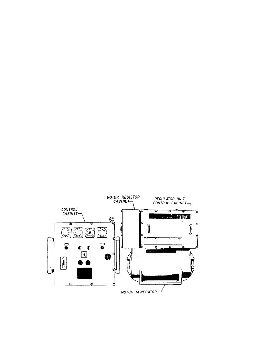
Figure 1-25.-Motor generator set with control equipment. |
|
||
| ||||||||||
|
|
 double row width, and a "Warning Do Not Lubricate
FREQUENCY REGULATORS
Bearings" instruction plate is mounted on the unit.
Frequency regulators are used to provide a regulated
frequency for frequency-sensitive equipment. To
MOTOR GENERATOR
troubleshoot frequency regulators, you need to have an
understanding of motor generators, as frequency and
voltage regulators are part of the control circuits for
In a 30-kW motor generator, since a constant speed
motor generators. The following paragraphs will discuss
is required for a constant frequency, the change in motor
motor generators and the troubleshooting of frequency
rotor current for changes in torque requirement is
regulators. Detailed troubleshooting charts for
accomplished through the external means of varying the
frequency regulators can be found in the service manual
tiring angle of three silicon controlled rectifiers (SCRs).
Motor Generator Set 30 KW, 440.450 V AC, 60/400
The basic operation of an SCR is as follows. The
Cycle, 3 Phase with Control Equipment.
SCR has a positive-negative-positive-negative (PNPN)
device structure and is the semiconductor equivalent of
a gas thyratron. It is constructed by making both an
30 kW CLOSELY REGULATED MOTOR
alloyed PN junction and a separate ohmic contact to a
GENERATOR SET
diffused PNP silicon pellet. Schematic representation of
the SCR is shown in figure 1-26. With reverse voltage
The 30-kW 440/450-volts ac, 60/400-Hz, 3-phase
(encircled polarities) impressed on the device (cathode
motor generator set (fig. 1-25) consists of a wound rotor
positive), it blocks the flow of current as in an ordinary
induction motor driving a synchronous generator.
rectifier. With positive voltage applied to the anode
Internal control circuits include voltage and frequency
(uncircled polarities), the SCR blocks the flow of
regulating systems, a motor controller (magnetic
current until either the forward breakdown voltage is
starter), and generator output circuit breakers. The unit
reached, or a suitable gate pulse is applied to the gate.
is designed for parallel operation with an identical unit.
In practical application, the positive pulse applied to the
Its housing is dripproof.
gate is used to control the firing of the SCR. At this point,
The wound rotor motor and generator is a
the SCR switches to a high-conduction state; the current
flow is limited only by the external circuit impedance
two-bearing unit with motor and generator rotors, plus
and supply voltage. The magnitude of gate impulse
a self-cooling fan mounted on a single shaft. The single
needed to turn on an SCR varies with temperature and
row ball bearings are prelubricated, double sealed,
Figure 1-25.-Motor generator set with control equipment.
1-22
|
|
Privacy Statement - Press Release - Copyright Information. - Contact Us |
