 |
|||
|
Page Title:
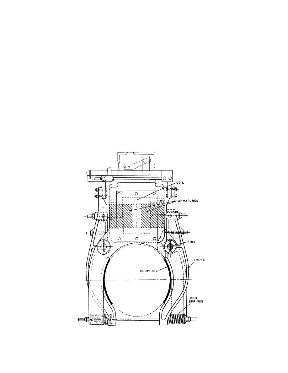
Figure 1-20.-Magnetic brake assembly. |
|
||
| ||||||||||
|
|
 The lowest leaf of brush contact 6 should just barely
contact. The wiping action keeps the surface bright and
touch contact 5. If the lower leaf hits the plate too soon,
clean, and thus maintains a low contact resistance.
bend the entire brush assembly upward slightly.
The contactor is operated by connecting the coil (2)
The contact dimensions should be measured with
directly across a source of dc voltage. When the coil is
the contactor in the OPEN position.
energized the movable armature (3) is pulled toward the
Refer to the manufacturer's instruction book when
stationary magnet core (4). This action causes the
making these adjustments.
contacts that carry current (5, 6, 7, and 1) to close with
a sliding action.
The main contacts (5 and 6), called brush contacts,
ELECTRIC BRAKES
are made of thin leaves of copper, which are backed by
several layers of phosphor bronze spring metal. A silver
An electric brake is an electromagnetic device used
brush arcing tip (7) is attached to the copper leaves and
to bring a load to rest mechanically and hold it at rest.
makes contact slightly before the leaf contact closes.
Aboard ship, electric brakes are used on motor-driven
The stationary contact (5) consists of a brass plate,
hoisting and lowering equipment where it is important
which has a silver-plated surface. Since the plating
to stop the motor quickly. The type of electric brakes
lowers the surface resistance, the contact surfaces
used depends on whether the motor is ac or dc and
should never be filed or oiled. If excessive current
whether a dc motor is series or shunt wound.
causes high spots on the contact, the high places maybe
AC SOLENOID BRAKE
smoothed down by careful use of a fine ignition-type
The magnetic brake assembly shown in figure 1-20
file.
is the main component of this electric brake. When the
You can check the operation and contact spacing by
coil is energized, two armatures are pulled horizontally
manually closing the contactor (be sure the power is off).
Figure 1-20.-Magnetic brake assembly.
1-15
|
|
Privacy Statement - Press Release - Copyright Information. - Contact Us |
