 |
|||
|
Page Title:
Figure 4-18.-Various speaker arrangements. |
|
||
| ||||||||||
|
|
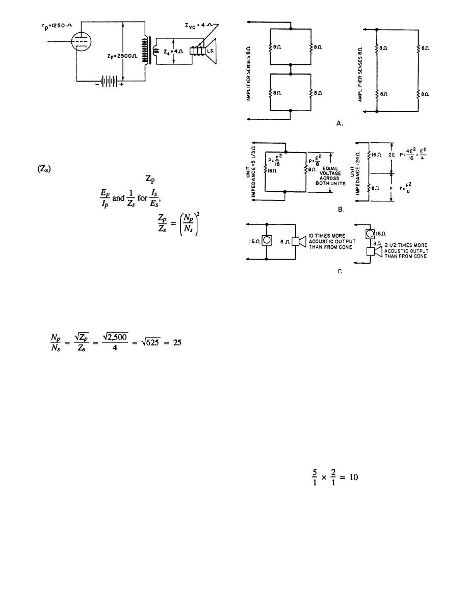 Figure 4-17.-Output transformer used as an Impedance
matching device.
The primary impedance (Z) of a matching
transformer is the ratio of rated primary voltage to rated
primary current. Similarly, the secondary impedance
is the ratio of rated secondary volts to rated
secondary current. Substituting
for
you get the impedance ratio
Thus, the ratio of the two impedances that a
transformer can match is equal to the turns ratio squared.
Also, the turns ratio is equal to the square root of the
impedance ratio. Example: Find the turns ratio for the
Figure 4-18.-Various speaker arrangements.
transformer shown in figure 4-17. The plate resistance
is 1,250 ohms and the primary impedance is twice as
much to permit maximum undistorted power output.
Such a combination might consist of an 8-ohm speaker
Solution:
and a 16-ohm speaker (fig. 4-18, view B). These two
speakers in parallel result in an impedance of 5 1/3
ohms. The voltage drop across the two speakers is the
same for both and the power division would be 2:1 in
favor of the 8-ohm speaker.
MATCHING SPEAKER LOADS
The alternate arrangement of series connection of
the unequal-impedance speakers produces a branch
Four equal impedances may be connected in a
impedance of 24 ohms with a power distribution that is
series-parallel arrangement to present the same
2:1 in favor of the 16-ohm speaker.
impedance as one speaker to the amplifier (fig. 4-18,
view A). In this case, the power delivered by the
The ratio of power conversion efficiencies of the
amplifier is divided equally among the four speakers.
8-ohm speaker to the 16-ohm speaker is at least 5:1.
For better reliability, a series connection of two speakers
Combining this output efficiency ratio with the actual
in parallel is preferred. Should one speaker open up, the
power taken by the two units gives
other three would continue to operate, but with a slight
power change. However, in a parallel arrangement of
two speakers in series (fig. 4-18, view A), if one speaker
opens up, its other series member becomes inoperative
and the system loses two speakers instead of one.
for the parallel connection (fig. 4-18, view C). This
shows that the 8-ohm speaker, taking twice as much
There may be times when speakers of unequal
electrical power as the 16-ohm speaker, is putting out 10
impedances are coordinated into an impedance-matched
system because they may be the only kind available.
times as much acoustic power.
4-17
|
|
Privacy Statement - Press Release - Copyright Information. - Contact Us |
