 |
|||
|
Page Title:
Figure 3-10.-Single-line diagram of a ship's service generator |
|
||
| ||||||||||
|
|
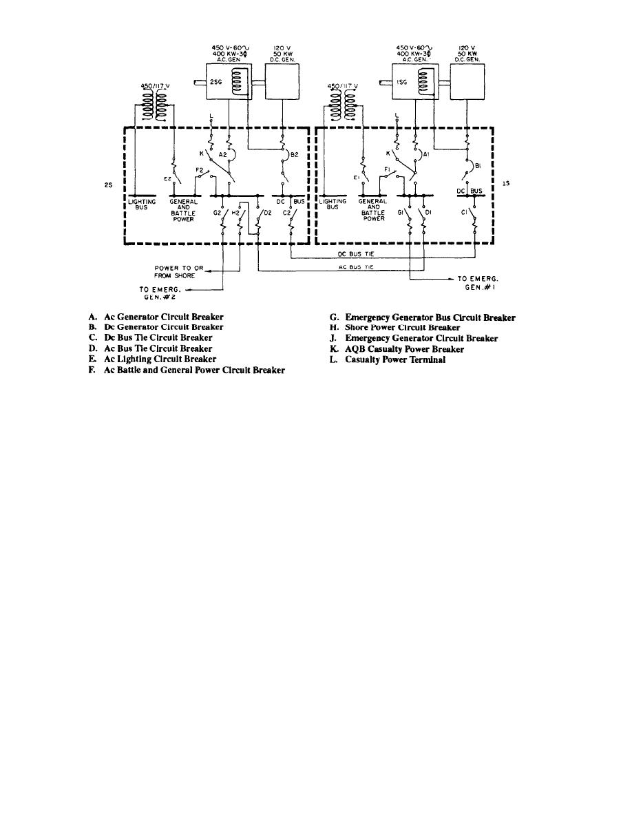 Figure 3-10.-Single-line diagram of a ship's service generator and switchboard interconnections.
system for a large ship. This diagram along with the
presents, in simplified form, the actual switching
information in the following paragraph present the
arrangements for paralleling the generators, for
functional operation of the overall system.
supplying the different power and lighting busses, and
for energizing the casualty power terminals.
The steering gear system (fig. 3-9) consists of one
complete synchro-controlled electric hydraulic system
for each rudder (port and starboard). The two steering
EQUIPMENT WIRING DIAGRAMS
systems are similar in all respects. They are separate
systems, but they are normally controlled by the same
Equipment wiring diagrams are used to
steering wheel (helm) and operate to move both port and
troubleshoot a system or a piece of equipment
starboard rudders in unison.
effectively. Where the block diagram is useful in
presenting the functional operation of a system or
SINGLE-LINE DIAGRAMS
equipment, the equipment wiring diagram gives a
detailed representation of various components. The
Single-line diagrams are also used to present a
wiring diagram shows the relative location of resistors,
general description of a system and to show how it
transformers, diodes, terminal boards, and so on, and
functions. The single-line diagram presents more detail
how each conductor is connected in the circuit.
concerning the system than the block diagram, and thus
requires less supporting text material.
Figure 3-11, view A, shows the main motor
controller wiring diagram for the steering system in
Figure 3-10 shows a single-line diagram of the
figure 3-9, The wiring diagram could be used to
ship's service generator and switchboard connections
troubleshoot, check for proper electrical connections, or
for a destroyer. This diagram shows the type of ac and
dc generators used to supply power for the ship and
completely rewire the controller.
3-16
|
|
Privacy Statement - Press Release - Copyright Information. - Contact Us |
