 |
|||
|
|
|||
| ||||||||||
|
|
 for each cable is shown on the ship's electrical wiring
prints.
The new cable marking system for power and
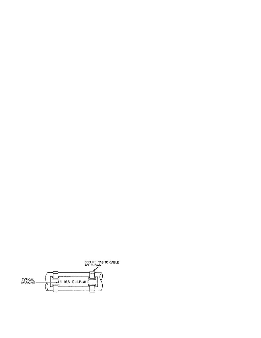
Metal tags embossed with the cable designation are
lighting cables consists of three parts in sequence:
used to identify all permanently installed shipboard
source, voltage, and service, and where practicable,
electrical cables. These tags (fig. 3-8) are placed on
destination. These parts are separated by hyphens.
cables as close as practicable to each point of
The letters used to designate the different services
connection, on both sides of decks, bulkheads, and other
are as follows:
barriers to provide identification of the cables for
maintenance and replacement.
CInterior communications
Two systems of cable marking (the old and the new)
DDegaussing
are in use aboard Navy ships. The old system uses the
color of the tag to show cable classification (red-vital,
GFire control
yellowsemivital, and gray or no colornonvital), and
KControl power
the following letters to designate power and lighting
LShip's service lighting
cables for the different services:
NNavigational lighting
CInterior communications
PShip's service power
DDegaussing
RElectronics
FShip's service lighting and general power
CPCasualty power
FBBattle power
ELEmergency lighting
GFire control
EPEmergency power
MSMinesweeping
FLNight flight
PElectric propulsion
MCCoolant pump power
RRadio and radar
MSMinesweeping
RLRunning, anchor, and signal lights
PPPropulsion power
SSonar
SFSpecial frequency power
FEEmergency light and power
In the new system, voltages below 100 volts are
Other letters and numbers are used with these basic
designated by the actual voltage; for example, 24 volts
letters to further identify the cable and complete the
for a 24-volt circuit. The numeral 1 is used to indicate
designation. Common marking of a power system for
voltages between 100 and 199; 2 for voltages between
successive cables from a distribution switchboard to
200 and 299; 4 for voltages between 400 and 499; and
load would be feeder, FB-411; main, 1-FB-411;
so on. For a three-wire (120/240) dc system or a
submain, 1-FB-411-A; branch, 1-FB-411-A1; and
three-wire 3-phase system, the number used indicates
subbranch, 1-FB-411-A1A. The feeder number, 411, is
the higher voltage.
indicative of the system voltage. The feeder numbers for
The destination of cables beyond panels and
a 117- or 120-volt system would range from 100 to 190;
switchboards is not designated except that each circuit
for a 220-volt system, from 200 to 299; and for a
alternately receives a letter, a number, a letter, and a
450-volt system, from 400 to 499. The exact designation
number, progressively, every time that it is fused. The
destination of power cables to consuming equipment is
not designated except that each cable to such equipment
receives a single-letter alphabetical designation,
beginning with the letter A.
Where two cables of the same power or lighting
circuit are connected in a distribution panel or terminal
box, the circuit classification is not changed. However,
the cable markings have a suffix number (in
Figure 3-8.-Cable tag.
parentheses) indicating the cable section. For example,
3-13
|
|
Privacy Statement - Press Release - Copyright Information. - Contact Us |
