 |
|||
|
Page Title:
Figure 3-29.--LVDT quadrature oscilitator. |
|
||
| ||||||||||
|
|
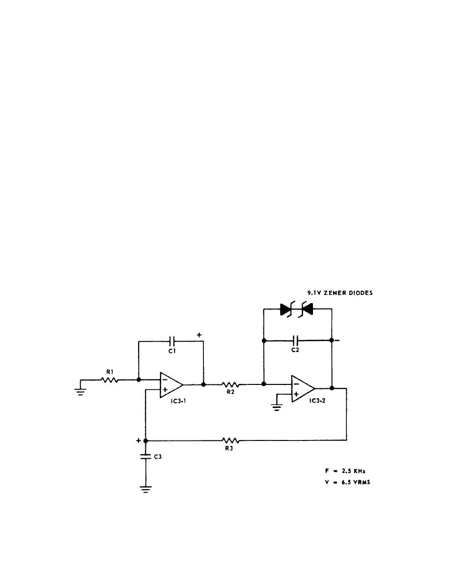 charged positive. The noninverting integrator IC3-1 will
core from its null position causes the voltage in one
charge C1 so its output goes positive. This positive
winding to increase, while simultaneously reducing the
voltage will cause the inverting integrator IC3-2 to
voltage in the other winding. The difference between the
charge its capacitor C2 and its output will go negative.
two voltages varies with linear position.
This negative voltage will discharge C3. This will con-
tinue until C3 is charged negative and then reverse,
LVDT Demodulator Card
causing the circuit to oscillate. The zener diodes clamp
the output and stabilize the amplitude so the output
The LVDT demodulator card supplies a constant
voltage is a stable 6.5 volts ac.
voltage ac excitation to the LVDT primaries and con-
verts the pitch and roll LVDT amplitude and phase
signals to a variable dc voltage. This is accomplished in
LVDT Demodulator
three separate circuits: the LVDT oscillator and the pitch
and roll demodulators.
The pitch and roll LVDT demodulator are identical
except for their gains. They are called phase sensitive
LVDT Oscillator
demodulators. The input to the demodulator is a vari-
able-voltage, variable-phase signal from the LVDT. This
The LVDT oscillator consists of a quadrature oscil-
signal is full-wave rectified and filtered and its output
lator and a power amplifier. The quadrature oscillator is
polarity is positive for signals out of phase with the
used to generate a constant-amplitude, constant-
reference and negative for signals in phase.
frequency sine wave. The power amplifier is a low-
output-impedance driver used to power the LVDT
Servo Amplifiers
primaries and the pitch and roll demodulator diode
switches.
The pitch and roll servo amplifier circuit cards are
identical except for the gains and servo compensation.
To understand the operation of the quadrature
Three inputs are summed into amplifier A1: LVDT,
oscillator, assume capacitor C3 of figure 3-29 is initially
Figure 3-29.--LVDT quadrature oscilitator.
3-20
|
|
Privacy Statement - Press Release - Copyright Information. - Contact Us |
