 |
|||
|
Page Title:
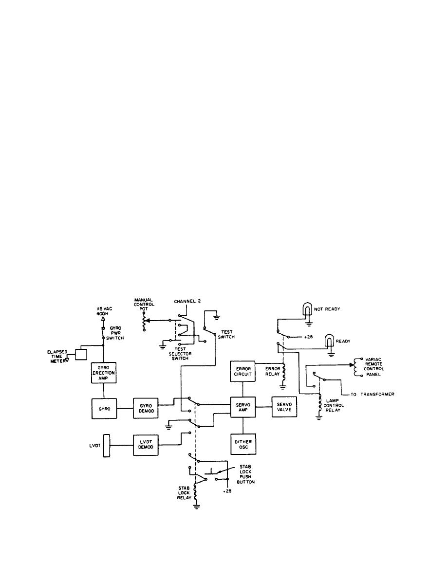
Figure 3-25.--Stabilization control-signal flow. |
|
||
| ||||||||||
|
|
 The op-amps used in this system are integrated
Figure 3-25 shows the signal flow in the servo loop.
circuit types using a configuration as shown in fig-
For example, in gyro normal mode, the gyro is powered
ure 3-26.
through the gyro power switch and the gyro erection
amp. The gyro synchro signal is converted to dc in the
An op-amp is a very high gain device, whose output
gyro demodulator and goes through the stab-lock relay
is the amplified difference between the inverting and
into the servo amplifier. The servo amplifier drives the
noninverting inputs. If feedback is added, the op-amp
servo valve that moves the cylinder to correct platform
will try to keep the voltage difference between the two
position. Any servo errors are compared in the error
inputs near zero.
circuit and trigger the error relay if the errors are large
The most common form of op-amp is the inverting
enough. The error relay will turn on the NOT READY
amplifier, as shown in figure 3-27. With the nonin-
light and turn off the GSI light. Stab-lock mode is similar
verting input tied to ground, the inverting input will be
and can also be followed on figure 3-25.
close to ground and is referred to as a virtual ground.
The higher the amplifier gain, the closer the point will
be to ground and for all computations it is assumed to
be ground. If an input voltage (Vin) is applied to the
circuit of figure 3-27, a current will flow in Rin. The
Operational amplifiers (op-amps) are used through-
amplifiers will amplify and invert the current and pro-
out the stable platform system as amplifiers, oscillators,
vide an output voltage. The output voltage will cause a
and comparators. To understand the different circuits,
current to flow in RF that will exactly cancel that flowing
you need to have a basic understanding of op-amps. An
operational amplifier is a high gain (10,000 or greater),
between them will be amplified until they do.
highly stable, dc amplifier. It is used most often to
perform analog computer functions such as summing
Multiple input circuits are similar to the inverting
amplifier circuit. The gain of each input is controlled by
and integration.
Figure 3-25.--Stabilization control-signal flow.
3-18
|
|
Privacy Statement - Press Release - Copyright Information. - Contact Us |
