 |
|||
|
Page Title:
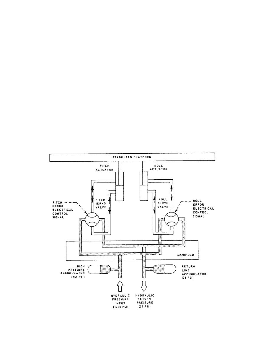
Figure 3-22.--Functional diagram of the stabilized platform assembly. |
|
||
| ||||||||||
|
|
 and used to drive the output in a direction to reduce the
Platform Configuration
error.
The stable platform consists of a flat top plate to
Assuming the input and output pots are initially
which the GSI is affixed. The top plate is attached to the
equal, then the difference in voltage is zero and there
base plate through a universal joint and a center post and
is no error. If the input command pot is moved, then
is moved by two hydraulic actuators that are coupled to
an error is generated. The amplifier amplifies the error
the top plate with two axis rod ends. The universal joints
and drives the power actuator that moves the output
and rod ends allow the platform to tilt in two axes. These
pot in a direction to reduce the error. Thus, in a
are designated pitch and roll to match ship motions for
feedback system, the output can be made to follow the
which the platform compensates. Figure 3-22 illustrates
input. This type of feedback system is often referred
a platform compensating for a roll motion, showing the
to as a servo loop.
major components of the platform.
The GSI stable platform uses two servo loops in
each axis, the gyro loop and the LVDT loop. In the gyro
SERVO LOOPS
loop, the gyro is used as an error detector sensing the
downward pull of gravity at its particular location. his
To understand the system operation, you need to
is termed earth's local gravity vector. The gyro lines
have an understanding of feedback control systems. A
itself up with this downward pull and any difference
feedback control system is a system where an input
between the gyro case and its internal reference provides
an output. This output is used as an error signal to correct
signal is compared with the system output and an error
the platform top to earth level.
signal is generated. This error signal is then amplified
Figure 3-22.--Functional diagram of the stabilized platform assembly.
3-16
|
|
Privacy Statement - Press Release - Copyright Information. - Contact Us |
