 |
|||
|
Page Title:
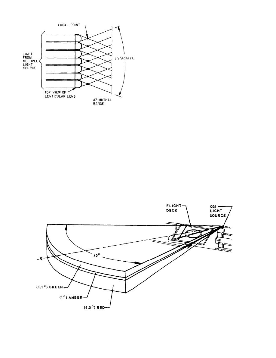
Figure 3-12.--Optical characteristics of the lenticular lens. |
|
||
| ||||||||||
|
|
 junction point for various cables of the system, as are all
junction boxes that are a part of the system.
SYSTEM OPERATION,
TROUBLESHOOTING, AND
MAINTENANCE
The following paragraphs provide information on
operating, checking-out, troubleshooting, and main-
taining the SGSI system. We will discuss some of the
things that can be done to keep the SGSI operating
efficiently.
When troubleshooting the SGSI system, you should
refer to the troubleshooting charts in the Stabilized Glide
Slope Indicator (SGSI) Mk 1 Mod 0 (Incorporating
Figure 3-12.--Optical characteristics of the lenticular lens.
Gyro Failure Alarm) for Air Capable and Amphibious
Assault Ships, NAVAIR 51-5B-2, technical manual. By
using the charts/tables in the technical manual for over-
attenuation. The top segment is colored green, the
all system checkout procedures, you will know what
middle segment is amber, and the large bottom segment
controls must be set during the performance of the
is colored red. When projected, the resulting glide path
checkout procedure. These tables also list the location
has the viewing zone as shown in figure 3-13. The GSI
of each control, the necessary instructions for the proper
cell was designed so 1 inch on its face is equal to 1 of
use of these controls, and the normal indications that
arc. Thus, the 1 amber is 1 inch on the cell face.
should be observed during the operation of these con-
trols. When an abnormal indication is observed during
The stowlock assembly provides a means of
the checkout procedures, certain additional procedures
securing the source light indicator in a fixed position
must be performed that use the controls available within
when the system is not in operation. The stowlock
the equipment to establish conditions that enable main-
assembly is located directly below the source light
tenance personnel to isolate malfunctions with a min-
indicator assembly and is secured to the deck-edge
imum use of test equipment. By using these procedures,
boom. The shipbuilder's junction box is used as a
Figure 3-13.--Viewing zone of glide slope indicator.
3-9
|
|
Privacy Statement - Press Release - Copyright Information. - Contact Us |
