 |
|||
|
Page Title:
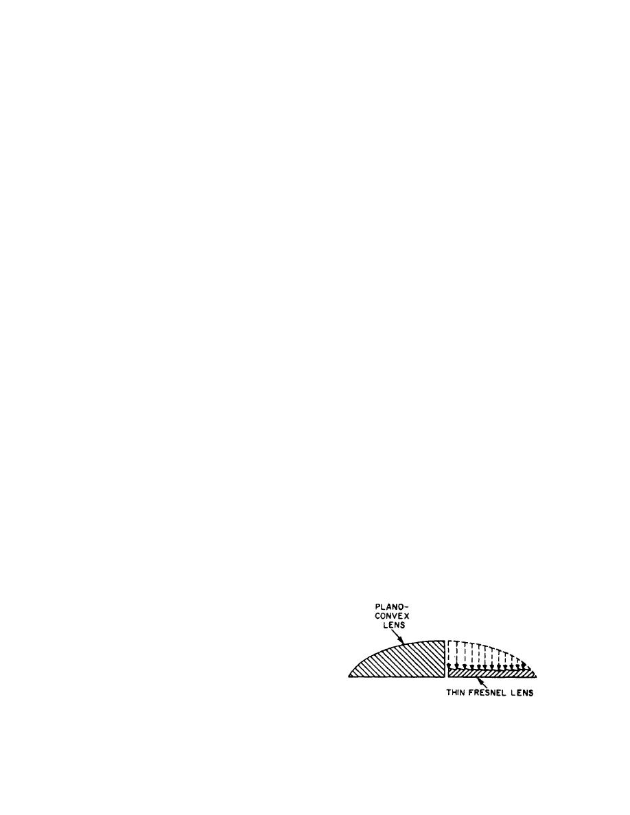
Figure 3-10.--Comparison of the physical characteristic of piano-convex lens and Fresnel lens. |
|
||
| ||||||||||
|
|
 area. This assembly contains a local gyro, gimbaled
pump to 1400 psi, filtered, and piped to the power supply
platform, hydraulic cylinders, and electrically operated
output line where it is available to the external system
servo valves. More information on the stabilized plat-
through a shutoff valve. On the return line, fluid is
form is given later in this chapter.
returned from the external system to the reservoir at a
reduced pressure of 75 psi. A shutoff valve is also used
in this low-pressure line. Electrical power is obtained
PRINCIPLES OF LENSES USED IN THE
from ship's power system and connected through the
GSI SYSTEM
motor controller and junction box. This assembly is
located as close as possible to the stabilized platform. It
There are two types of lenses used in the optical
provides hydraulic fluid at 1400 psi to the hydraulic
portion of the GSI system: the Fresnel lens and the
actuator on the stabilized platform. The motor and con-
lenticular lens. A discussion of the principles of the
troller operate on 440-volt, 3-phase received from
piano-convex lens is provided so the physical charac-
normal ship's power supply. The temperatures witches
teristics of this type of lens may be compared with the
(not shown) operate the OVERTEMP light on the
physical characteristics of the Fresnel lens.
remote control panel. Also, a pressure switch in the
hydraulic pump discharge line will close at 1200 psi. If
PLANO-CONVEX LENS
not closed, the pressure switch will de-energize the
electronic panel assembly on low oil pressure.
A piano-convex lens has a plane, or flat, surface and
Hydraulic fluid heaters in the oil reservoir maintain the
a spherical surface. This type of lens is a positive, or
temperature at approximately 70F5.
collective, lens; that is, a lens in which the light rays are
collected at a focus to form an image. The radius of the
TRANSFORMER ASSEMBLY
spherical surface of the lens is known as the radius of
curvature.
The transformer assembly is a weathertight
enclosure mounted within 3 feet of the stabilized plat-
FRESNEL LENS
form. An interconnecting cable, which is part of the
transformer assembly, connects the transformer
The Fresnel lens is a lightweight and relatively thin
assembly to the GSI. This assembly is located as close
sheet of transparent Lucite material. The refraction of
as possible to the stabilized platform. Its purpose is to
light rays by the Fresnel lens is collective, as in a
step down the voltage for the source light (GSI) from
piano-convex lens; however, the Fresnel lens differs
115 volts ac to 18.5 volts ac.
from a piano-convex lens, as shown in figure 3-10. One
surface of the Fresnel lens consists of a number of
GLIDE SLOPE INDICATOR
stepped facets. These facets are circular, concentric
ASSEMBLY
grooves that extend from the center of the lens to the
edges. The slope of each facet is independent of the
The GSI assembly consists of two major sub-
slope of all other facets. These slopes are designed to
assemblies: the mounting base assembly and the
provide a perfect focus of the light rays that pass through
indicator assembly. The indicator assembly is supported
the lens. Thus, the Fresnel lens provides an advantage
in the mounting base assembly, which is mounted on the
over a piano-convex spherical lens in that the plano-
stabilized platform. The incoming system cable con-
convex spherical lens causes spherical aberration of
nects at the rear of the right-hand heater compartment.
The mounting base assembly provides the means to
accurately position the indicator assembly in relation to
the landing pad. The mounting base is then secured in
this position by the retractable plunger. Indicator eleva-
tion is controlled by the elevation adjustment knob. The
GSI sits in the trunnions of the mounting base assembly.
STABILIZED PLATFORM
ASSEMBLY
Figure 3-10.--Comparison of the physical characteristic of
The stabilized platform assembly is mounted to the
ship's deck in close proximity to the helicopter landing
piano-convex lens and Fresnel lens.
3-7
|
|
Privacy Statement - Press Release - Copyright Information. - Contact Us |
