 |
|||
|
Page Title:
Figure 3-9.--Hydraulic pump assembly. |
|
||
| ||||||||||
|
|
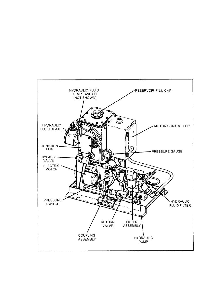 HYDRAULIC PUMP ASSEMBLY
control and indicators for operating and monitoring the
SGSI system from a remote location. It contains the
The hydraulic pump assembly (fig. 3-9) is a self-
READY and NOT READY lights deseribed previously.
contained medium-pressure, closed-loop system used
The panel also contains an OVERTEMP light to indicate
to supply hydraulic pressure for the stabilized platform.
when the hydraulic fluid is heated to a temperature
This assembly consists of an electric pump motor, a
higher than 135F5, a source failure light to indicate
coupling unit, a hydraulic pump reservoir, valves,
piping, and an electrical system. All components are
that one or more of the GSI source lights are burned out,
mounted on a steel base and comprise a complete self-
a variable transformer to control the intensity of GSI
contained 1400-psi hydraulic power supply.
light, and a panel illumination control. A standby light
Hydraulic fluid is stored in a reservoir and piped to
will be energized when the main switch on the electronic
a motor-driven pump. The output is pressurized by the
enclosure assembly is on.
Figure 3-9.--Hydraulic pump assembly.
3-6
|
|
Privacy Statement - Press Release - Copyright Information. - Contact Us |
