 |
|||
|
Page Title:
Figure 3-5.--Stabilized platform assembly, functional diagram. |
|
||
| ||||||||||
|
|
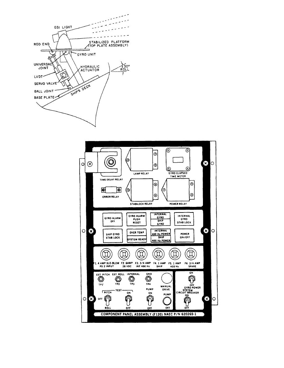 fluid to enter the hydraulic actuator (fig, 3-5), thereby
leveling the platform and thus canceling the error signal.
When this occurs, a READY light is actuated on the
remote control panel. If the system develops a mal-
function and the error signal is not canceled, an error-
sensing circuit will light the NOT READY light on the
remote control panel and turn off the GSI.
In the previous paragraphs, we discussed the normal
mode of operation in the electronics portion of the
system. The stabilization lock feature (stab-lock relay)
tests and aligns the GSI. Referring to figure 3-6, you will
buttons and two test switches, one of which is pitch-
off-roll.
As previously mentioned, the error signal in the
normal mode goes through a stab-lock relay. When the
stab-lock button is pushed, the normal error signal
supplied from the gyro is stopped at this point (see
Figure 3-5.--Stabilized platform assembly, functional diagram.
Figure 3-6.--Compenents panel assembly (P/O electronics enclosure-F100) controls and indicators.
3-4
|
|
Privacy Statement - Press Release - Copyright Information. - Contact Us |
