 |
|||
|
Page Title:
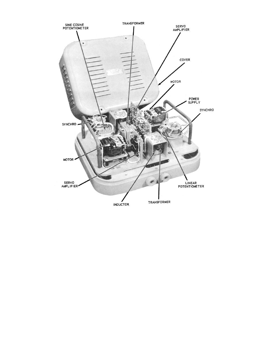
Figure 2-14.Cross and headwind computer assembly. |
|
||
| ||||||||||
|
|
 40.133
Figure 2-14.Cross and headwind computer assembly.
which the windspeed voltage from the other circuit is
speed of the wind. The function of components is the
applied.
same as in the synchro amplifier just described,
except that this mechanism positions a potentiometer
The sine-cosine potentiometer contains four
instead of a synchro transmitter.
stacked sections, one for each of the desired
WIND DIRECTION CIRCUIT
components
of windspeed. The signals from the angled deck
sections lag the signals from the straight deck
The wind direction circuit converts the synchro
sections by 10
signal output of the wind direction transmitter into
volt-ages proportional to the desired crosswind and
The dc power supply is a highly regulated unit
head-wind components of windspeed. This is done
that converts 115-volt, 60-Hz power to a 40-volt dc
with a mechanism similar to the one used in the
output.
windspeed circuit, which positions a sine-cosine
potentiometer, to
2-15
|
|
Privacy Statement - Press Release - Copyright Information. - Contact Us |
