 |
|||
|
Page Title:
Figure 2-11.--Block diagram of a synchro signal amplifier. |
|
||
| ||||||||||
|
|
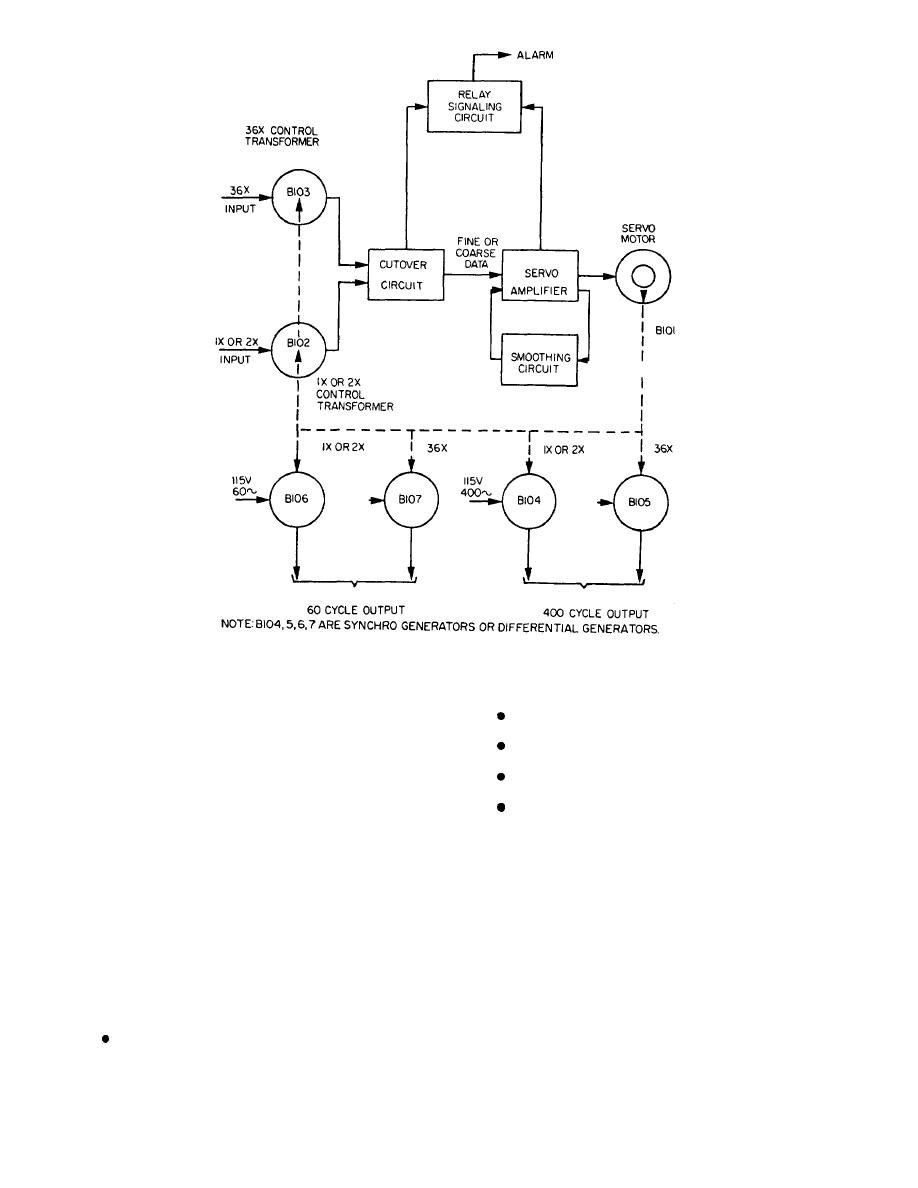 Figure 2-11.--Block diagram of a synchro signal amplifier.
1 speed
36 speed
E- and F-type synchro signal amplifiers will be
discussed in this section of the chapter. The major
2 speed
difference between the two types is that the type E
2 and 36 speed
operates with 60-Hz supply and input. The type F
operates with 400-Hz supply and input signals. The
The E- and F-type synchro signal amplifiers consist
of subassemblies housed in a dripproof case. These
different supply and input frequencies require that the
cases are the same on both types of synchro signal
E- and F-type units use different synchro control trans-
amplifiers. The internal subassemblies are similar in
formers, servomotors, synchro capacitors, and
design. The only differences are the ones previously
amplifiers. Both types have provisions for four output
covered.
synchros: two for 60-Hz and two for 400-Hz trans-
The subassembly is easily accessible through a front
mission. Both types of synchro signal amplifiers are
access door in the case that can be opened by loosening
designed to provide for input and output transmission at
screws in the door. The door has hinges and supporting
any of the following combinations of speeds:
chains so it can be lowered and used as a service plat-
1 and 36 speed
form for the internal subassembly. An alarm switch, a
2-9
|
|
Privacy Statement - Press Release - Copyright Information. - Contact Us |
