 |
|||
|
|
|||
| ||||||||||
|
|
 operate in parallel without speed droop with changing
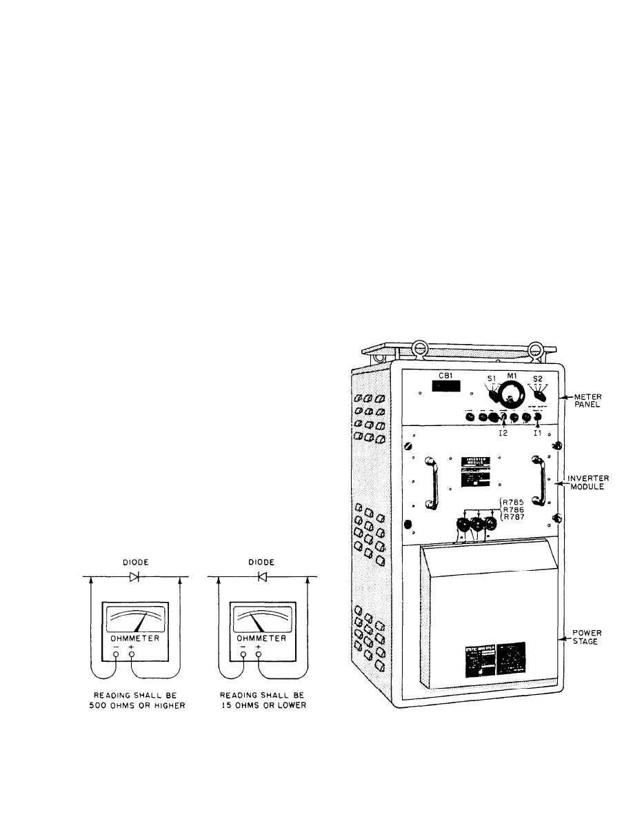
and the negative lead is connected to the cathode side,
load and to divide the load (kW) evenly between them.
the ohmmeter will indicate a low value (15 ohms or
less). With the ohmmeter leads reversed across the
SAFETY
diode, a higher reading will be obtained (Refer to
fig. 1-36) A front to back ratio of 10 to 1 is usually
The inherent dangers of rotating machinery are kept
considered a good diode.
to a minimum; however, it remains the responsibility of
Various test setups have been devised for transis-
supervisory personnel to ensure that personnel
tors, and often they are included in the manufacturer's
performing preventive and corrective maintenance are
technical manual.
thoroughly acquainted with the possible hazards
A key to good maintenance that should be stressed
involved. Except during supervised maintenance, all
is familiarity with the manufacturer's technical manual.
doors and covers should be in place. Since considerable
semiconductor application is made here, test equipment
settings and proper soldering techniques must be
STATIC INVERTER
observed when maintenance is required.
The need for a highly dependable, static, 400-Hz
MAINTENANCE
power supply led to the development of the 4345A static
inverter.
The 3-M system provides adequately for preventive
The model 4345A static inverter delivers a closely
maintenance on the motor generator. No corrective
regulated 400-Hz, 3-phase, 120-volt output from a
maintenance should be attempted without a thorough
250-volt dc source. Two single-phase static inverters are
understanding of the pertinent sections of the
manufacturer's technical manual. Troubleshooting
charts are of great value when employed with test
procedures in identification and isolation of problem
areas.
One test that may be of some assistance is that used
for silicon diodes. With this test, the silicon diodes may
be tested without removal from the circuit by the use of
a low-range (0-500 ohms) ohmmeter. The test is
performed by readings taken with the ohmmeter leads
connected across the diode in the opposite or reverse
direction. This means that the positive lead of the
and then to the opposite side. Comparison of the reading
will indicate the condition of the diode. When the
positive lead is connected to the anode side of the diode
Figure 1-36.-Diode test.
Figure 1-37.-Static inverter.
1-30
|
|
Privacy Statement - Press Release - Copyright Information. - Contact Us |
