 |
|||
|
|
|||
| ||||||||||
|
|
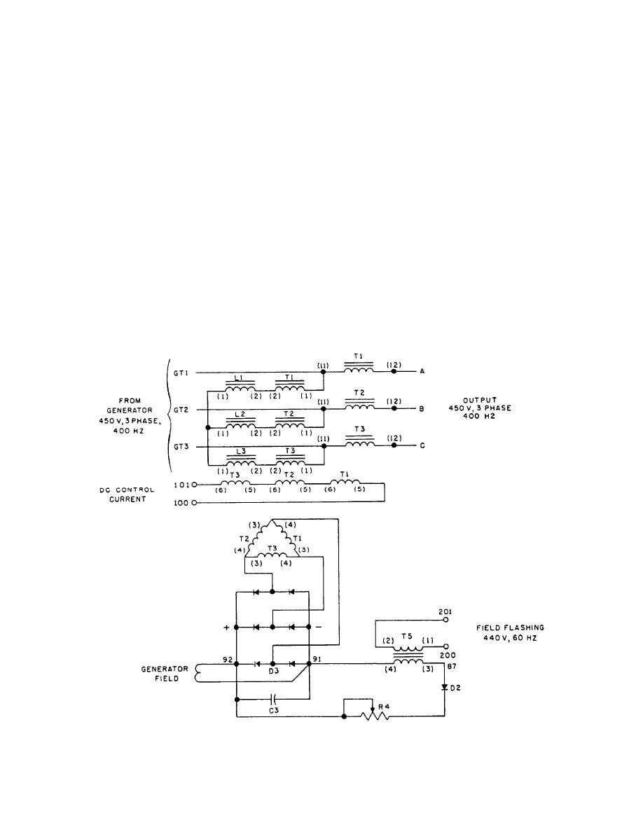 conjunction, excite the common secondary (3-4
STATIC EXCITER
windings of T1, T2, and T3) to provide generator field
The static exciter (fig. 1-30), which derives its
excitation.
operating power from the generator output, is designed
When a load is applied to the output, current will
to supply the correct amount of field current to the
flow in the current primaries of T1, T2, and T3 of the
generator, to maintain a constant output voltage to a load
SCPT. A current transformer action will take place with
that varies in magnitude or has a lagging power factor.
the common secondary 3 and 4 of T1, T2, and T3 of the
During the motor-starting period, there is no generator
SCPT that will add to the field excitation current caused
output, and the generator field current is supplied by the
in the secondary by voltage primary 1 and 2 of the SCPT.
field-flashing circuit. The field-flashing circuit derives
This action is explained later. L1, L2, and L3 are chokes.
its operating power from the 60-cycle supply voltage.
The field excitation current will rise in proportion
his voltage is reduced to 30 volts by transformer T5,
to the application of load and lagging power factor.
rectified by diode D2, and faltered by capacitor C3. The
Adding a dc control winding on the SCPT will change
dc current then flows through dropping resistor R4 and
the coupling between primary and secondary windings.
excites to the generator field.
This winding controls the generator output voltage. This
The saturable current-potential transformer (SCPT,)
is accomplished by connecting the output of the voltage
(fig. 1-30) has two sets of primary windings exciting a
regulator to the dc control winding.
common secondary. The primary windings of T1, T2,
The signal developed in the power section of the
and T3 in series with the load are current primaries.
voltage regulator (fig. 1-27) is used as dc control to the
Those primary windings in parallel (T1, T2, and T3)
static exciter.
are potential primaries. Both primaries, acting in
Figure 1-30.-Static exciter.
1-26
|
|
Privacy Statement - Press Release - Copyright Information. - Contact Us |
