 |
|||
|
Page Title:
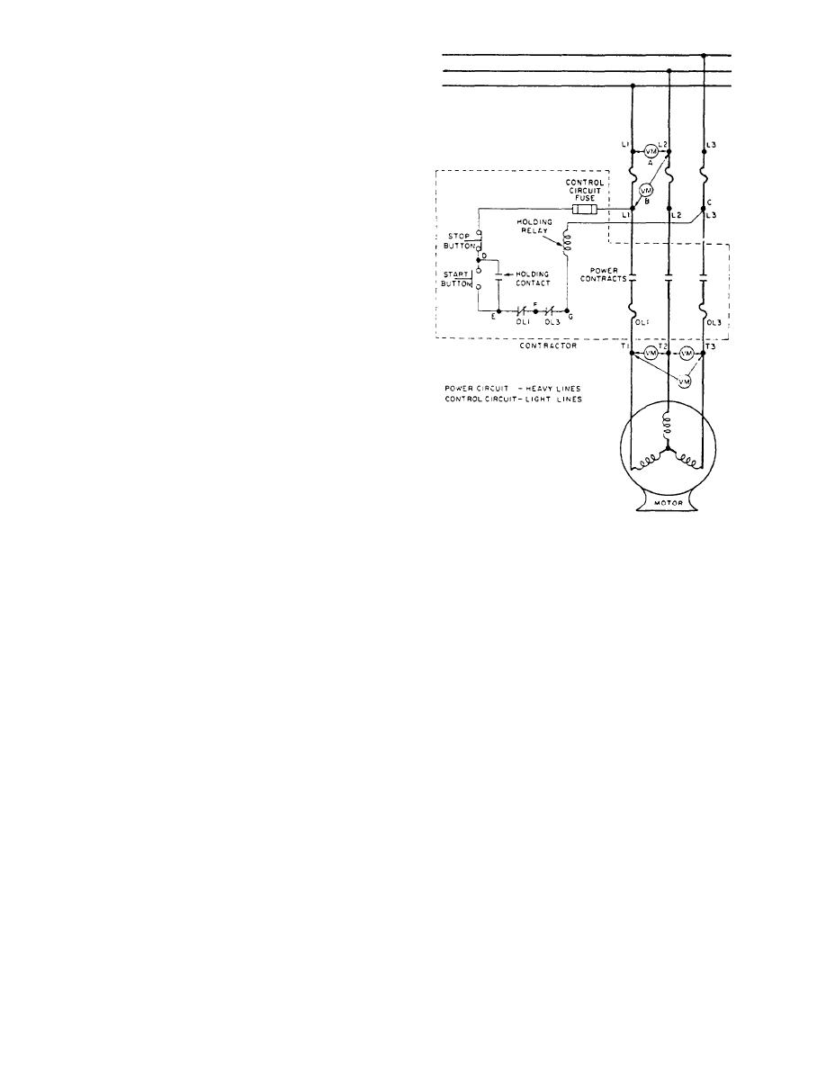
Figure 1-24-Troublesboottng a 3-phase magnetic tine starter. |
|
||
| ||||||||||
|
|
 the dc brake construction is of solid metals and requires
no lamination as does the ac magnetic brake.
CONTROLLER TROUBLESHOOTING
Although the Navy maintains a policy of preventive
maintenance, sometimes trouble is unavoidable. In
general, when a controller fails to operate, or signs of
trouble (heat, smoke, smell of burning insulation, and so
on.) occur, the cause of the trouble can be found by
conducting an examination that consists of nothing more
than using the sense of feel, smell, sight, and sound. On
other occasions, however, locating the cause of the
problem will involve more detailed actions.
Troubles tend to gather around mechanical moving
parts and where electrical systems are interrupted by the
making and breaking of contacts. Center your attention
in these areas. See table 1-1 for a list of common
troubles, their causes, and corrective actions.
When a motor-controller system has failed and
pressing the start button will not start the system, press
the overload relay reset push button. Then, attempt to
start the motor. If the motor operation is restored, no
further checks are required. However, if you hear the
controller contacts close but the motor fails to start, then
check the motor circuit continuity. If the main contacts
do not close, then check the control circuit for continuity.
Figure 1-24-Troublesboottng a 3-phase magnetic tine starter.
An example of troubleshooting a motor-controller
electrical system is given in a sequence of steps that may
be used in locating a fault (fig. 1-24). We will start by
connections within the controller. However, if voltage
analyzing the power circuit.
is indicated at all three terminals, then the trouble is
either in the motor or lines leading to the motor.
POWER CIRCUIT ANALYSIS
CONTROL CIRCUIT ANALYSIS
When no visual signs of failure can be located and
an electrical failure is indicated in the power circuit, you
must first check the line voltage and fuses. Place the
Suppose the overload reset buttons have been reset
voltmeter probes on the hot side of the line fuses as
and the start switch is closed. If the power contacts do
shown at position A. A line voltage reading tells you that
not close, then the control circuit must be checked. The
your voltmeter is operational and that you have voltage
testing procedure is as follows:
to the source side of the line fuses, L1-L2. You also may
1. Check for voltage at the controller lines, L1, L2,
check between L1-L3 and L2-L3. To check the fuse in
and L3.
line L1, place the voltmeter across the line fuse as shown
2. Place the voltmeter probes at points C and D
at position B between L1-L2. A voltage reading shows
(fig. 1-24). You should have a voltage reading when the
a good fuse in L1. Likewise, check the other two fuses
stop switch is closed and a no-voltage reading when the
between L1-L3 and L2-L3. A novoltage reading would
stop switch is open. The conditions would indicate a
show a faulty fuse.
good stop switch.
If the line fuses check good, then check the voltage
between terminals T1-T2, T2-T3, and T1-T3. The
3. Next, check the voltage between points C and
E. If you get a no-voltage reading when the start switch
controller is faulty if there aren't voltmeter readings on
is open and a voltage reading when the start switch is
all three of the terminal pairs, and you would then
closed, then the start switch is good.
proceed to check the power contacts, overloads, and lead
1-18
|
|
Privacy Statement - Press Release - Copyright Information. - Contact Us |
