 |
|||
|
Page Title:
Figure 1-23.-Connections for dynamic braking of a shunt-wound dc motor. |
|
||
| ||||||||||
|
|
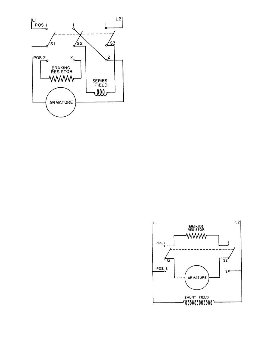 the switch arms are in position 1, the armature is dis-
connected from the line and connected to the resistor.
The shunt field remains connected to the line. As the
armature turns, it generates a countervoltage that forces
the current through the resistor. The remainder of the
action is the same as described for the circuit in fig-
ure 1-22.
Although dynamic braking provides an effective
means of slowing motors, it is not effective when the
field excitation fails or when an attempt is made to hold
heavy loads; without rotation, the countervoltage is
zero, and no braking reaction can exist between the
armature and the field.
Dc Magnetic Brake
Magnetic brakes are used for complete braking
protection. In the event of field excitation failure, they
Figure 1-22.-Connections for dynamic braking of a
will hold heavy loads. A spring applies the brakes, and
series-wound dc motor.
the electromagnet releases them.
Disk brakes are arranged for mounting directly to
from a controller. With the switch arms in position 1,
the motor end bell. The brake lining is riveted to a steel
the motor operates from the line. When the switch arms
disk, which is supported by a hub keyed to the motor
are in position 2, the resistor is connected in series with
shaft. The disk rotates with the motor shaft.
the field, and, at the same time, the field coil connection
The band-type brake has the friction material
to the armature is reversed. Thus, as long as the armature
fastened to a band of steel, which encircles the wheel or
turns, it generates a countervoltage, which forces cur-
drum and may cover as much as 90 percent of the wheel
rent through the resistor and the series field. Although
surface. Less braking pressure is required and there is
the direction of current flow through the armature is
less wear on the brake lining when the braking surface
reversed (because of the countervoltage), the direction
is large.
through the series field coil is not reversed. When
operating in this way, the motor is essentially a generator
The dc brakes are operated by a solenoid similar in
that is being driven by the momentum of the armature
design to the ac solenoid brake (fig. 1-20), except that
and the mechanical load. Energy is quickly consumed
in forcing current through the resistor, and the armature
stops turning.
The time required to stop the motor maybe varied
with different resistor values. The lower the resistance,
the faster the braking action. If two or more resistors are
connected by switches, the braking action can be varied
by switching in different load resistors. Usually, the
same braking resistors that are used to stop the motor
are also used to reduce the line voltage during
When dynamic braking is used with a dc shunt-
wound motor, resistance is connected across the
armature (fig. 1-23).
Switches S1 and S2 are part of a double-pole
double-throw (DPDT) circuit breaker assembly. When
Figure 1-23.-Connections for dynamic braking of a
the switch arms are connected to position 2, the armature
shunt-wound dc motor.
is across the line, and motor operation is obtained. When
1-17
|
|
Privacy Statement - Press Release - Copyright Information. - Contact Us |
