 |
|||
|
Page Title:
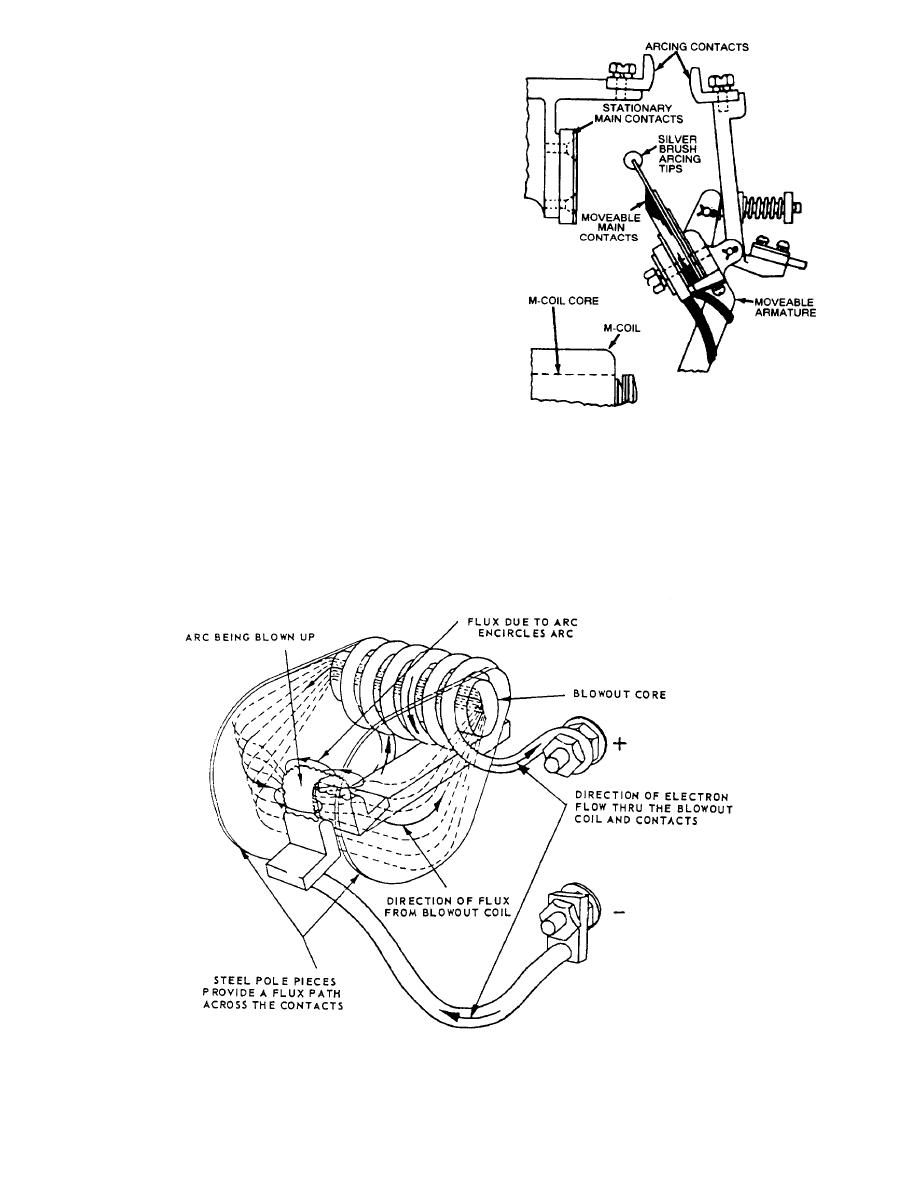
Figure 1-18.-Action of a magnetic blowout coil. |
|
||
| ||||||||||
|
|
 blowout coils overcome this condition by providing a
magnetic field, which pushes the arc away from the
contact area.
The magnetic blowout operation is shown in fig-
ure 1-18. It is important that the fluxes remain in the
proper relationship. Otherwise, if the direction of the
current is changed, the direction of the blowout flux will
be reversed and the arc will actually be pulled into the
space between the contacts.
When the direction of electron flow and flux areas
shown in figure 1-18, the blowout force is upward. The
blowout effect varies with the magnitude of the current
and with the blowout flux. The blowout coil should be
chosen to match the current so the correct amount of
flux may be obtained. The blowout flux across the arc
gap is concentrated by the magnetic path provided by
the steel core in the blowout coil and by the steel pole
pieces extending from the core to either side of the gap.
Figure 1-19.Detailed view of arcing contacts.
Arcing Contacts
Shunt-type contractors will handle up to 600
amperes at 230 volts. The blowout shield has been
removed in this detailed view. The diagram shows the
The shunt contactor shown in figure 1-19 uses a
main sections of the contactor. The arcing contacts (1)
second set of contacts (1) to reduce the amount of arcing
are made of rolled copper with a heavy protective coat-
across the main contacts (5 and 6) when closing. The
ing of cadmium. These contacts are self-cleaning be-
numbers that are in parentheses are indicated on the
figure.
cause of the sliding or wiping action following the initial
Figure 1-18.-Action of a magnetic blowout coil.
1-14
|
|
Privacy Statement - Press Release - Copyright Information. - Contact Us |