 |
|||
|
Page Title:
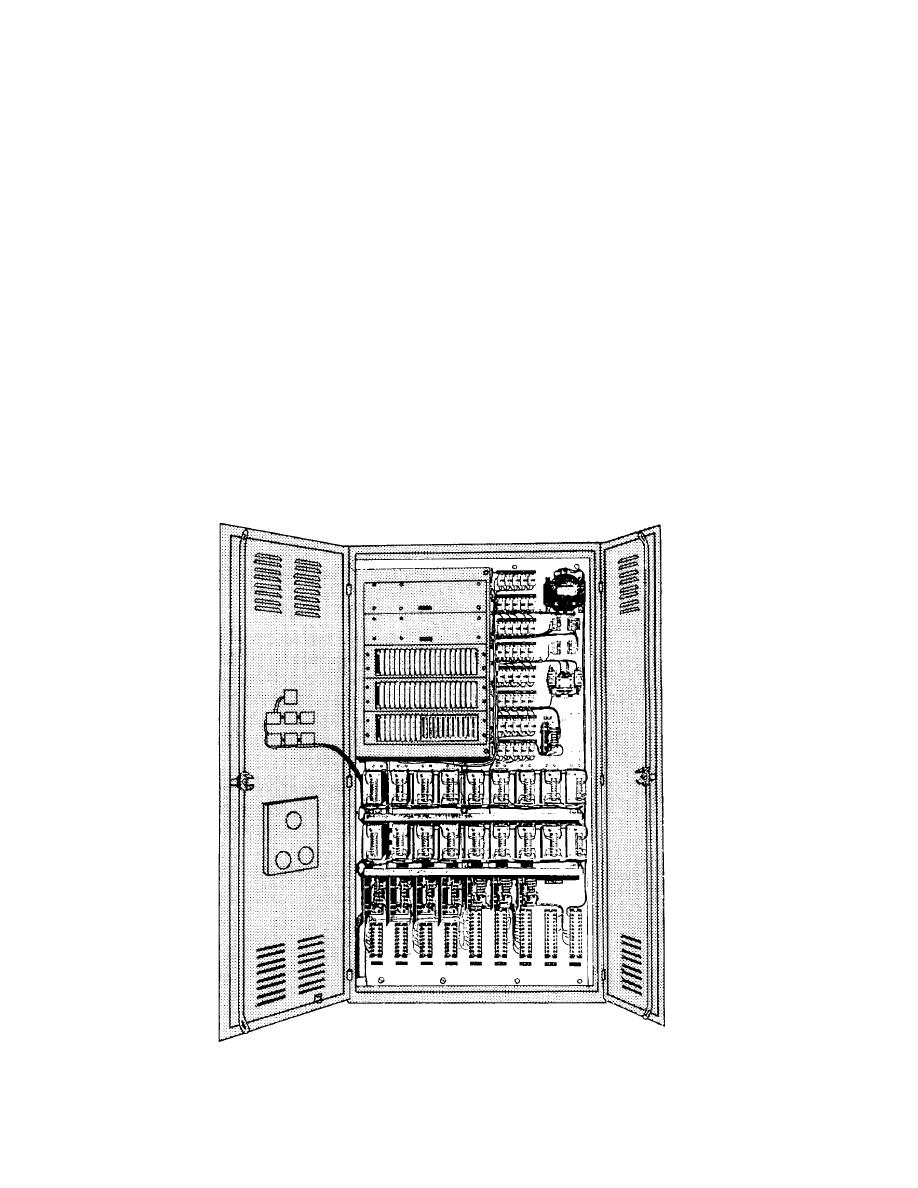
Figure 1-13.-A static logic panel for a cargo elevator. |
|
||
| ||||||||||
|
|
 connected in the line at start and are cut out in steps as
less space requirements. A typical static logic panel
the motor accelerates to the running speed.
found aboard ship is shown in figure 1-13.
Motors used with cargo winches and other deck
Although there are logic symbols other than AND
and OR, they all incorporate solid-state devices, For
auxiliaries operate over a wide range of speeds. Since
more information on solid-state devices refer to NEETS,
the speed of a dc motor with a constant load varies
module 7.
almost directly with the voltage, stages of line resistance
are used to make speed changes and to limit the current
DC CONTROLLERS
at starting. These stages of line resistance are connected
The starting of all dc motors, except those with
in various combinations, manually selected by a master
fractional horsepower, requires a temporary placing of
switch operating with a magnetic controller. Thus, the
resistance in series with the armature circuit to limit the
operator directly controls the amount of resistance in the
high current at start. The starting resistance cannot be
line and the resulting speed of the motor at all times.
removed from the line until the motor has accelerated in
One-Stage Acceleration
speed and the counter electromotive force has increased
Figure 1-14 shows a typical dc controller. The con-
to limit the current to a safe value.
Auxiliary motors located below deck generally
nections for this motor controller with one stage of
drive constant-speed equipment. A rheostat in the shunt
acceleration are shown in figure 1-15. The letters in
field circuit may be provided to furnish speed control
parentheses are indicated on the figures. When the start
for motors operating with ventilation fans, forced draft
button is pressed, the path for current is from the line
blowers, and certain pumps where conditions may
terminal (L2) through the control fuse, the stop button,
require operation at more than one speed.
the start button, and the line contactor coil (LC), to the
line terminal (L1). Current flowing through the
Small motors use one stage of starting resistance in
the line for a few seconds to limit the starting current.
contactor coil causes the armature to pull in and close
With larger motors, two or more stages of resistance are
the line contacts (LC1, LC2, LC3, and LC4).
Figure 1-13.-A static logic panel for a cargo elevator.
1-10
|
|
Privacy Statement - Press Release - Copyright Information. - Contact Us |
