 |
|||
|
Page Title:
Figure 11-16.--Nonreversing across-the-line starter for steering gear pump motor. |
|
||
| ||||||||||
|
|
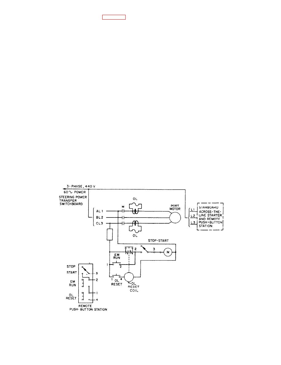 In an emergency you can run the motor (even
maintained-contact master switch (fig. 11-16). The
though the overload relays have been tripped) by
starter is supplied with 440-volt, 3-phase, 60-Hz power
holding the EM-RUN push button closed with the
from the steering power transfer switchboard located in
START push button in the operated position. If the
the steering gear room.
overload condition has not been corrected, the motor
The pump motor on either power unit is started or
will operate only as long as the EM-RUN push button
stopped by operating the maintained-contact push but-
is held closed.
ton on the associated push-button station to the desired
position. When the maintained-contact start push button
is pressed, the circuit is completed to the contactor
OPERATION AND MAINTENANCE
operating M coil of the line contactor. This action
energizes the operating M coil and closes the contactor
Operating instructions and system diagrams are
in the motor starter to connect the motor to the line.
normally posted near the steering gear. The diagrams
The motor will continue to run until the M coil is
describe the various procedures and lineups for
de-energized because of loss of voltage, tripping of the
operation of the steering gear.
overload relay, or pressing of the stop push button.
Maintenance should be performed according to
The motor starter is provided with overload and
your ship's PMS requirements for steering gears.
low-voltage release (LVR) protection. The overload
relays are of the thermal type, similar to those installed
SUMMARY
in the anchor windlass starter (discussed later in this
chapter under the operation of the destroyer anchor
windlass). The low-voltage release protection is pro-
In this chapter, you were given information on
vided by the maintained-contact master switch.
auxiliary equipment, including the components,
operating procedures, troubleshooting procedures,
If the operating M coil is de-energized due to failure
and maintenance procedures. You were also
of the line voltage or tripping of an overload relay, the
introduced to the fundamentals of cathodic protection
contactor will reclose and restart the motor when volt-
systems, including their operation, logs, and
age is restored or when the overload relays are reset by
maintenance.
the reset push button.
|
|
Privacy Statement - Press Release - Copyright Information. - Contact Us |
