 |
|||
|
Page Title:
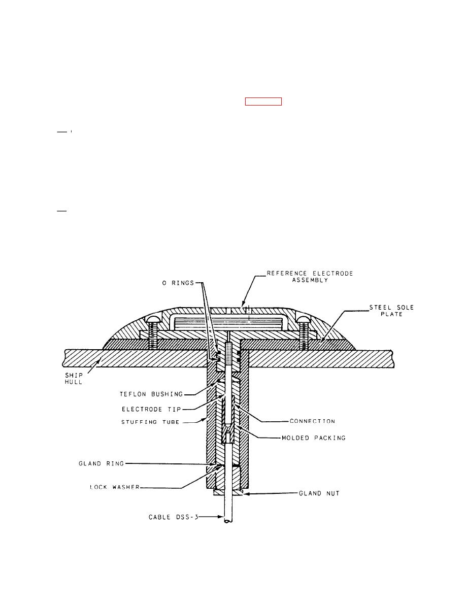
Figure 11-12.--Reference electrode assembly. |
|
||
| ||||||||||
|
|
 are available in the following three sizes: 2 feet (40
Anode to anode, anode to electronic log
amperes), 4 feet (75 amperes), and 8 feet (150
equipment, and anode to reference cell
separation should be a minimum of 40 feet.
amperes).
Installation of the anodes should be placed to
Anodes should not be installed within 15 feet
maintain a uniform potential throughout the under-
of a sea chest or pipe discharge.
water hull. The following is a list of anode locations:
Reference Electrode.-- The reference electrode
-- Placement should be at least 5 feet below the
of a silver mesh screen that has been treated with silver
light-load waterline.
chloride. It is bolted to the exterior hull of the ship and
One- and two-screw ships will have one set of
is insulated from the ship by a polyvinyl chloride
holder. A stuffing tube is used to pass the cable from
anodes located more than 10 feet, but less than
the electrode through the hull to the controller. The
50 feet, forward of the propeller plane.
controller measures the potential of the hull versus the
-- Four-screw ships will have two anodes located
reference electrode, and signals the power supply to
between the forward and after propeller planes,
increase or decrease current output as required. This
is to reduce the potential difference between the hull
one port and one starboard.
potential and the preset desired potential. Two
Anodes should be mounted in an area that
reference electrodes are installed for each controller.
experiences minimum water turbulence and
One reference electrode is selected for the primary
control; the other reference electrode serves as an
that is protected from mechanical damage.
11-12
|
|
Privacy Statement - Press Release - Copyright Information. - Contact Us |
