 |
|||
|
Page Title:
Figure 10-34.--Gearing diagram of an indicator-transmitter. |
|
||
| ||||||||||
|
|
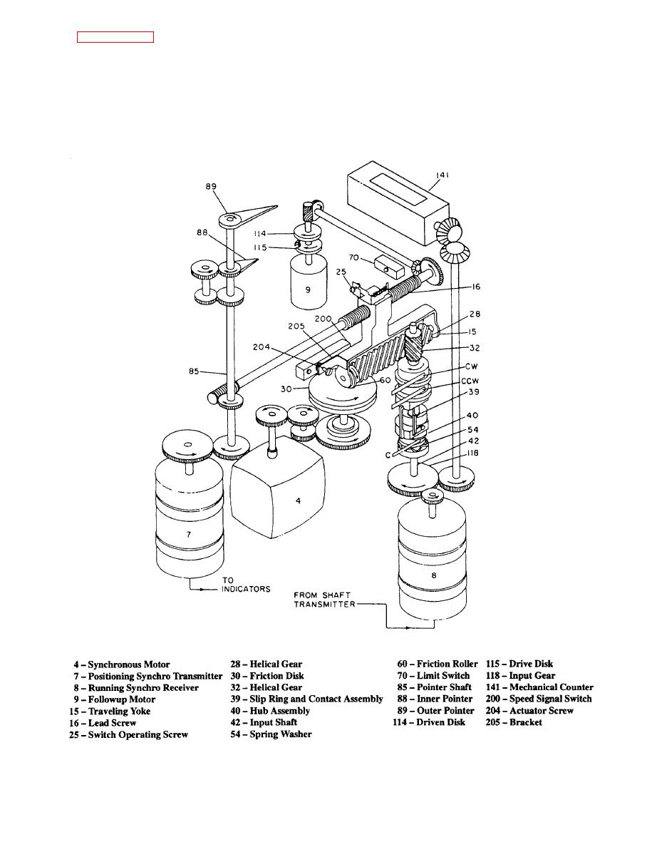 The two concentric revolving pointers indicate on
Figure 10-34 is the gearing diagram of an
a dual-marked fixed dial the output in rpm of the
indicator-transmitter. The indicator-transmitter
speed-measuring mechanism. The inner scale, marked
consists of a running synchro receiver, a speed-
for each 100 rpm only, is indexed by short pointer 88.
measuring mechanism, a positioning synchro
The outer scale, calibrated from zero to 100 rpm with
transmitter, a revolution counter, two pointers, a dial,
numerals for each 5 rpm, is indexed by long pointer
and a backing signal.
10-20
|
|
Privacy Statement - Press Release - Copyright Information. - Contact Us |
