 |
|||
|
Page Title:
Figure 10-32.--Simplified sketch of a follow-up control showing application of a gear differential. |
|
||
| ||||||||||
|
|
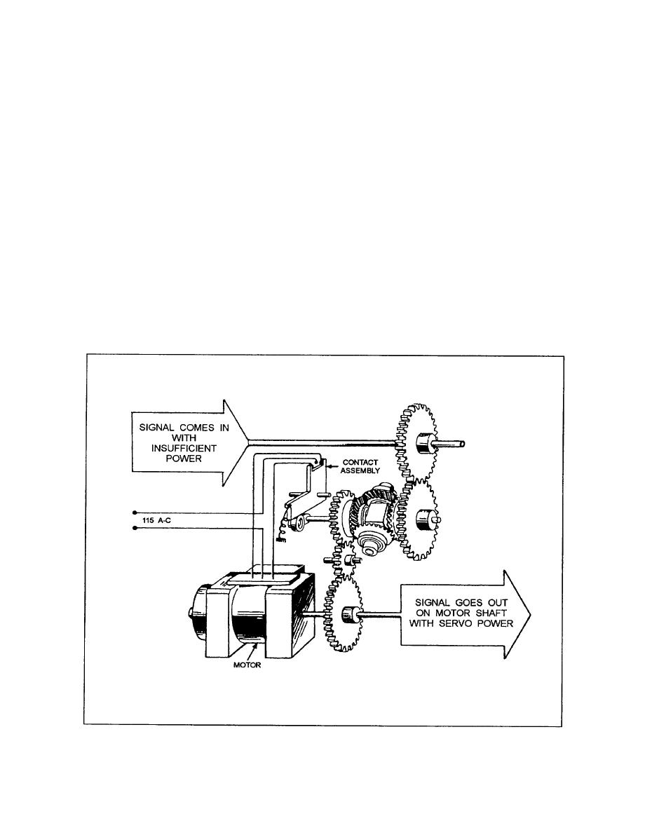 the other side of the differential. This second operation
METERING AND INDICATING
SYSTEMS
is known as the servo response.
When there is a difference between the input and
Metering and indicating systems provide
the output, the spider of the differential turns. As this
continuous information from remote sensors on the
happens, the spider shaft operates a set of controls
position, status, or condition of a particular system.
which control the action of the servomotor in such a
The sensors used in metering and indicating systems
way that the motor drives its side of the differential in
include switches, salinity cells, mechanical linkages,
a direction opposite to that taken by the input. That is,
synchros, pressure sensors, and various types of
the servo always drives to reduce the difference, or
temperature sensors. Indicator panels used with the
error, to zero.
systems include meters, dials, lamps, and other
While you may not work specifically with
indicators that provide a readout of the desired
mechanical computers as an IC Electrician, you will
information. Some systems include alarms, which are
actuated when predetermined conditions exist.
When working with mechanical gear trains, it will
help to look for the simple machines within the
The operation of some of the various metering
equipment; this will help in the understanding of the
and indicating systems will be discussed in the
whole complex machine and will enable you to more
quickly isolate trouble areas.
following paragraphs.
|
|
Privacy Statement - Press Release - Copyright Information. - Contact Us |
