 |
|||
|
|
|||
| ||||||||||
|
|
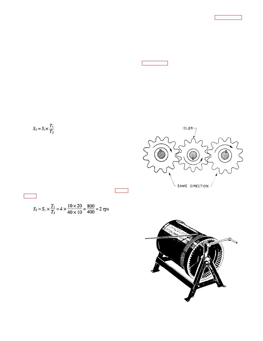 driven gear turn in the same direction. Figure 10-23
which mesh with the 40 teeth on wheel B. Wheel A
shows you how this works.
will have to rotate four times to cause B to make one
revolution. Wheel C is rigidly fixed on the same shaft
with B. Thus, C makes the same number of
MAGNIFYING FORCE WITH GEARS
revolutions as B. However, C has 20 teeth and meshes
with wheel D, which has only 10 teeth. Hence, wheel
Gear trains are used to increase the M.A. In fact,
D turns twice as fast as wheel C. Now, if you turn A
wherever there is a speed reduction, the effect of the
at a speed of four revolutions per second, B will be
effort you apply is multiplied. Look at the cable winch
rotated at one revolution per second. Wheel C also
in figure 10-24. The crank arm is 30 inches long, and
moves at one revolution per second and causes D to
the drum on which the cable is wound has a 15-inch
turn at two revolutions per second. You get out two
radius. The small pinion gear has 10 teeth, which mesh
revolutions per second after having put in four
with the 60 teeth on the internal spur gear. You will
revolutions per second. Thus, the overall speed
find it easier to figure the M.A. of this machine if you
reduction is 2/4--or 1/2--which means that you got
think of it as two machines.
half the speed out of the last driven wheel that you put
First, figure out what the gear and pinion do for
into the first driven wheel.
you. The theoretical M.A. of any arrangement of two
You can solve any gear speed-reduction problem
with the following formula:
Where
S1 = speed of first shaft in train
S2 = speed of last shaft in train
T1 = product of teeth on all drivers
T2 = product of teeth on all driven gears
Now use the formula on the gear train of figure
Almost any increase or decrease in speed can be
obtained by choosing the correct gears for the job. For
example, the turbines on a ship have to turn at high
speeds--say 5800 rpm--if they are going to be
efficient. But the propellers, or screws, must turn
rather slowly--say 195 rpm--to push the ship ahead
with maximum efficiency. So, a set of reduction gears
is placed between the turbines and the propeller shaft.
When two external gears mesh, they rotate in
opposite directions. Often you will want to avoid this.
Put a third gear, called an idler, between the driver and
the driven gear. But do not let this extra gear confuse
you on speeds. Just neglect the idler entirely. It does
not change the gear ratio at all, and the formula still
applies. The idler merely makes the driver and its
|
|
Privacy Statement - Press Release - Copyright Information. - Contact Us |
