 |
|||
|
Page Title:
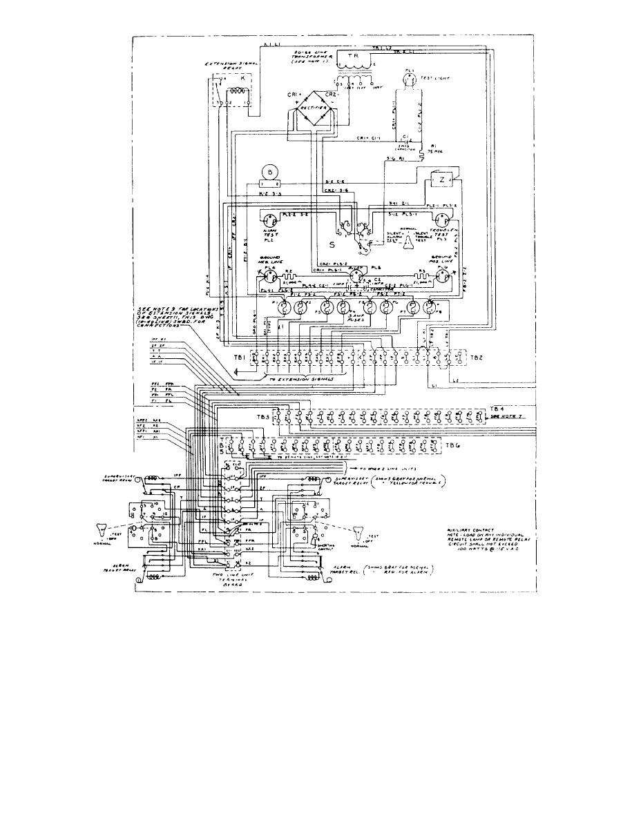
Figure 9-17.--Schematic of an alarm switchboard. |
|
||
| ||||||||||
|
|
 the switchboard or in one of the lines. When a ground
common alarm section are an audible volume control,
is sensed, one of the lamps will illuminate.
a tone generator, a battery, a battery charger, the
common board, and the power supply.
VISUAL-AUDIBLE SWITCH.-- The visual-
GROUND DETECTION INDICATORS.--
audible switch is a two-position switch. When it
is placed in the VISUAL position, no audible alarm
The two ground detection indicators are provided to
will be received, only the alarm silence indicator will
indicate when a positive or negative ground exists in
9-16
|
|
Privacy Statement - Press Release - Copyright Information. - Contact Us |
