 |
|||
|
Page Title:
Figure 9-14.--B-51 alarm panel. |
|
||
| ||||||||||
|
|
 27.304
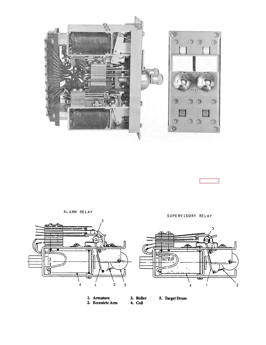
The alarm relay has a U-shaped frame. Inside the
into square openings in the face of the panel. The two
frame is a magnetic coil, an armature, and an
three-position rotary switches are mounted above the
indicator drum. On top of the frame, two pairs of
alarm relays. The two supervisory relays, with their
contact springs are mounted (fig. 9-15).
indicator drums, are mounted above the switches. A
The magnetic coil of the alarm relay is wound with
bell and buzzer are connected in the relay circuits to
13,500 turns of wire to a resistance of 1325 ohms. The
provide audible alarms.
9-13
|
|
Privacy Statement - Press Release - Copyright Information. - Contact Us |
