 |
|||
|
Page Title:
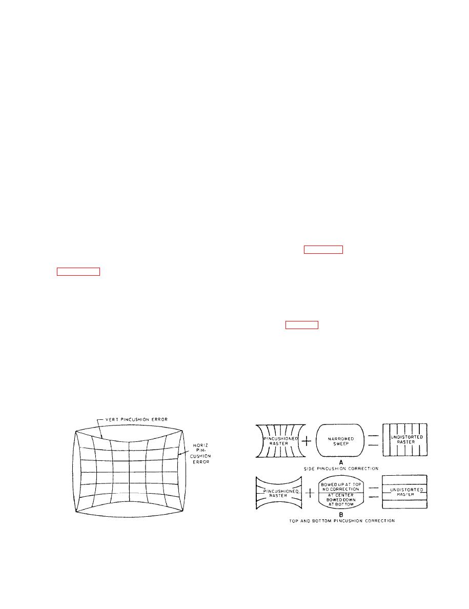
Figure 8-16.--Effects of dynamic pincushion corrections. |
|
||
| ||||||||||
|
|
 "anti-pincushion" correction yokes. These yokes
The color convergence circuits provide a
secondary control over the electron beam of each gun.
produce a somewhat distorted magnetic field that
Convergence of the three electron beams to exact
compensates for any pincushion error caused by a flat
locations on the face of the three-gun CRT is necessary
screen surface. Another method of correcting
to produce good monochrome and color images.
pincushion error in monochrome receivers is to place
permanent magnets in the drift space between the
Other differences, such as automatic color control,
tuning indicators, and color reception indicators, serve
deflection yoke and the screen. The magnetic field
to simplify the operation of front-panel controls.
produced by each magnet "bucks" pincushion error,
and an undistorted raster is obtained. Although these
Pincushioning
methods work well for single-gun CRTs, more
sophisticated means are required to correct distortion
Modem color receiver design calls for the use of
in three-gun tubes. For example, the magnetic fields
a wide-angle deflection yoke. Wider deflection angles
produced by the permanent magnets would not exert
allows the CRT to be shortened. This allows the
equal force on each gun, due to the triangular gun
cabinet to be made smaller. In an attempt to provide a
construction.
larger viewing area, receivers are made with flat-
Modem color receivers use dynamic correction
surface rectangular CRTs. Unfortunately wide-angle
circuits to modify the height and width of the raster.
deflection with flat-surfaced CRTs causes some
Pincushioning along each side of the raster is
problems. These are bowed scan lines and elongated
corrected by subtracting from the horizontal
corners at the edge of the raster. This distortion,
referred to as "pincushioning," is caused by projecting
deflection width at the beginning and end of the
the raster onto a flat surface and using wide deflection
vertical scan (fig. 8-16, view A). In contrast,
angles.
pincushion error is corrected at the top and bottom of
the raster by adding to the vertical sweep. This
when a cross-hatch pattern is projected onto the
addition occurs at the center of each line near the top
screen. Notice that the vertical and horizontal lines
and bottom of the raster. When the sweep pulses are
passing through the center of the raster are not
modified in this manner, the pincushion error is
noticeably distorted. As the scan goes away from the
corrected along both sides and the top and bottom of
center, distortion occurs along the top, bottom, and
the raster (fig. 8-16, view B).
both sides of the raster. In effect, the raster becomes
Although many circuits are presently used to
"stretched" at the corners. This stretching is due to the
provide dynamic pincushion correction, the end result
greater distance the electron beams have to travel at
is always the same; that is, predistortion of the sweep
the outer edges.
current waveform. Basically, this involves decreasing
In monochrome receivers, where a single-gun
the change rate of the sweep current as it approaches
CRT is used, geometric distortion can be corrected by
its maximum values.
cross-hatch pattern.
8-18
|
|
Privacy Statement - Press Release - Copyright Information. - Contact Us |
