 |
|||
|
Page Title:
Figure 7-29.--Schematic diagram of two stations in parallel. |
|
||
| ||||||||||
|
|
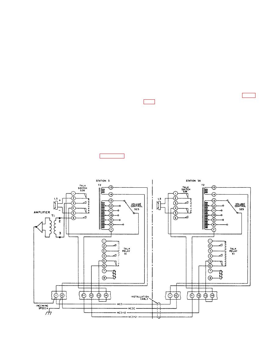 is depressed, the voice coil leads of the loudspeaker are
from push-pull amplifier arrangements are high gain
and low distortion. Transformer coupling not only
shifted from terminals 7 and 13 of the secondary of T2
allows the amplifier to be isolated, but also provides
to input transformer T1 of the amplifier. Thus, talk relay
K1 is operated, which applies plate voltage to the
amplifier at the talking station and places the amplifier
OPERATION
in the ready condition. The voice signals are amplified
and applied to terminals 14 and 15 of T2 at the listening
To call a particular station, depress the station
station and appear across terminal 7 of T2 and the
selector push button for that station, depress the talk
moving contact of volume control S25, and from there
switch, and speak directly into the reproducer grille.
to the loudspeaker. The amplifier in the listening unit is
Release the talk switch to listen. When the conversation
in standby.
is completed, depress the release push button to restore
The operation of two intercom stations in parallel is
the selector switch.
illustrated by the simplified schematic diagram in figure
To answer a call from another station, simply listen
to the conversation, and answer by depressing the talk
be heard at both stations 3 and 3A, and replies can be
switch; it is not necessary to operate the station selector
made from either station. Either station can call a third
switch. The call light on your unit will be illuminated to
station, but both stations cannot call at the same time.
indicate your station is being called by another station.
When talk switch S26 at station 3 is depressed to
If the call light remains illuminated at the completion of
transmit a message, talk relay K1 at station 3A is
your conversation, depress the talk switch and remind
operated to open the circuit to the loudspeaker and
the calling station to depress the release push button.
prevent acoustic feedback (not shown).
The audio circuit between two stations is illustrated
Incoming speech lines 1 and 1C of station 3 are
by the simplified schematic diagram in figure 7-29. The
connected to terminals 15 and 14, respectively, on
talk switches at both stations are shown in the restored
transformer T2.
(listen) position. When talk switch S26 at either station
7-29
|
|
Privacy Statement - Press Release - Copyright Information. - Contact Us |
