 |
|||
|
|
|||
| ||||||||||
|
|
 To check a power-supply choke, use the voltmeter
to read the output voltage of the choke. If the reading is
excessively high, the choke has an internal short within
the choke. If there is no output voltage, the choke has an
open winding or a winding shorted to the case or core.
TRANSISTORS.-- To check a suspected transis-
tor, use an in or out of circuit transistor test set, or sub-
stitute the suspected transistor with a known good transistor.
continuity checks between switch terminals, or a
voltmeter can be used to measure the voltages at the
switch terminals.
INDICATOR LAMPS.-- To check a suspected
indicator lamp, you must replace it with a new lamp or
one known to be good.
CENTRAL AMPLIFIER SYSTEM
(TWO-WAY)
The two-way central amplifier announcing system
provides two-way transmission of orders and informa-
tion using central amplifiers. One example of a two-way
central amplifier announcing system is the AN/SIA-
120. The AN/SIA-120 comprises the circuit 29MC
(sonar control and information amounting system) and
provides two-way communications between the sonar
control room and various remote stations. The sonar
control room transmits to loudspeakers at the remote
stations, and the remote stations transmit to the
loudspeakers in the sonar control room.
The AN/SIA-120 operates on 115-volt, 60-cycle,
single-phase ship's service power. The major
components of the system are the control rack and the
additional sound equipment used with the system.
The control rack has input facilities for one portable
microphone and five microphone control stations. The
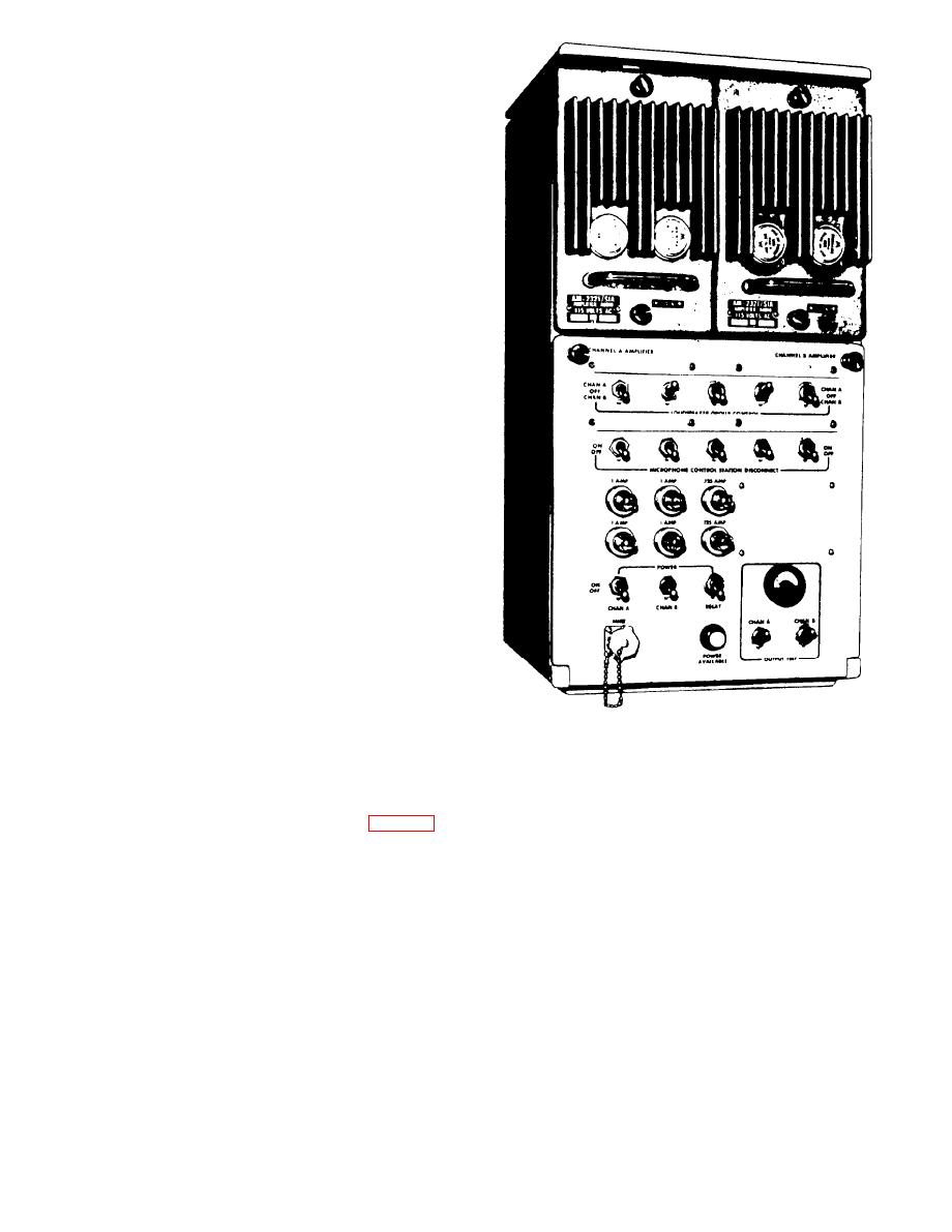
CONTROL RACK
control rack also has the facilities for connecting five
The control rack for the AN/SIA-120 (fig. 7-26) is
individual loudspeaker groups to the outputs of the
a bulkhead-mounted enclosure containing two identical
amplifiers. In addition, the rack has a circuit with an
amplifier channels, A and B. Each channel uses one
amplifier priority control feature, which will connect an
self-contained modular audio-frequency amplifier
alarm signal provided from an external source to the
capable of 20-watt output power. The amplifiers are
inputs of the amplifiers while inhibiting operation from
located in two compartments in the upper half of the
the microphone control stations.
rack The bottom half of the rack is a control panel. All
the system's switching, testing controls, and indicators
Audio-Frequency Amplifiers
are located on the front of the control panel. The system
The two amplifiers located in the upper half of the
control relays, relay power supply, and various other
control rack are used for complete amplification of the
components are mounted on a bracket behind the control
microphone outputs. The inputs to the amplifiers are
panel. Terminal boards, which are used for making
parallel connected. The output transistors are physically
connections to the ship's wiring, are located on the lower
locatcd on the front of the panel. This design allows the
rear wall of the rack and are accessible by opening the
use of the whole front panel as a heat sink, providing
control panel.
|
|
Privacy Statement - Press Release - Copyright Information. - Contact Us |
