 |
|||
|
Page Title:
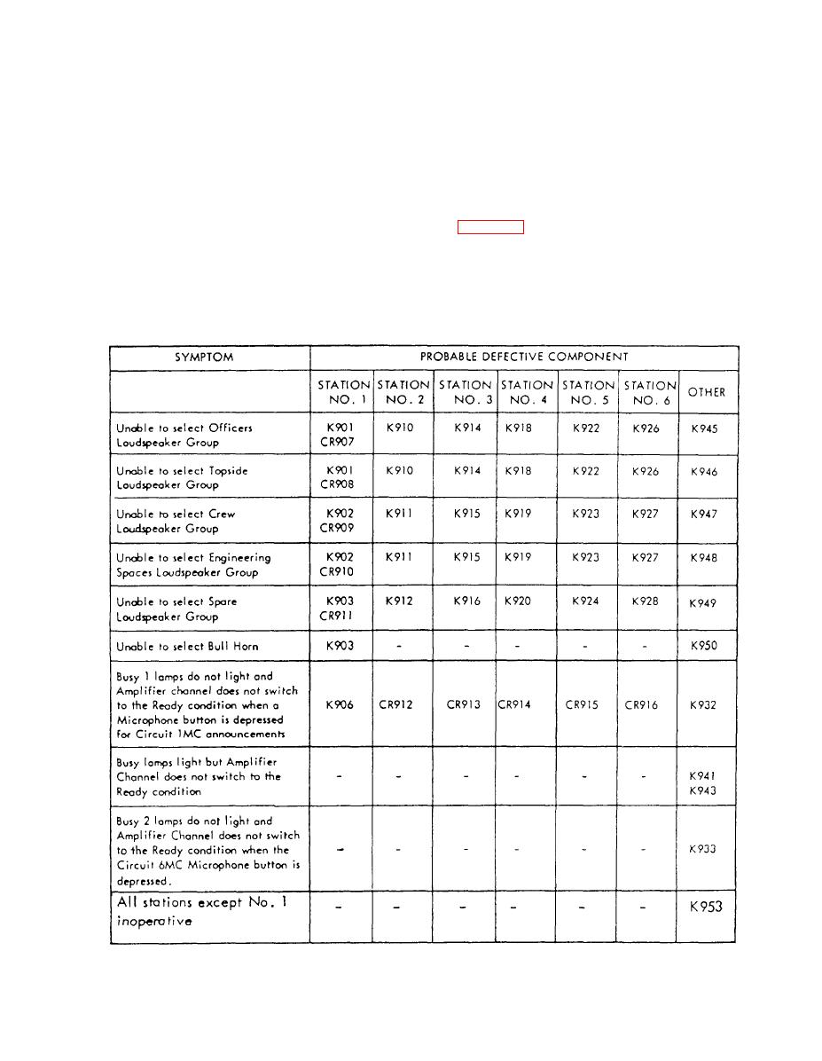
Table 7-2.--Microphone Control Station Trouble Chart |
|
||
| ||||||||||
|
|
 rack. If power is not available, check the position of the
localized by using the test meters and meter test switches
included in the control and power racks. Also, the use
supply switch on the main IC switchboard.
of duplicate oscillator, preamplifier, and power
If power is available, check all fuses and switches
amplifier assemblies permits the testing or repair of one
associated with the system. If a fuse failure is indicated,
assembly while the other assembly remains in active
replace the fuse. If the new fuse burns out immediately,
service, thereby avoiding the necessity for shutting
do not replace it a second time until the cause has been
down the system.
corrected. A check of the switches on both the control
If the entire announcing system is inoperative, the
rack and the microphone control stations may show that
trouble is probably in the ship's power supply or wiring
one or more are not in the proper position.
from the ship's power supply. Check the power available
indicator on the control rack. This indicator, unless it is
defective, will be lighted when power is available to the
system. These tables show some of the more common
7-22
|
|
Privacy Statement - Press Release - Copyright Information. - Contact Us |
