 |
|||
|
Page Title:
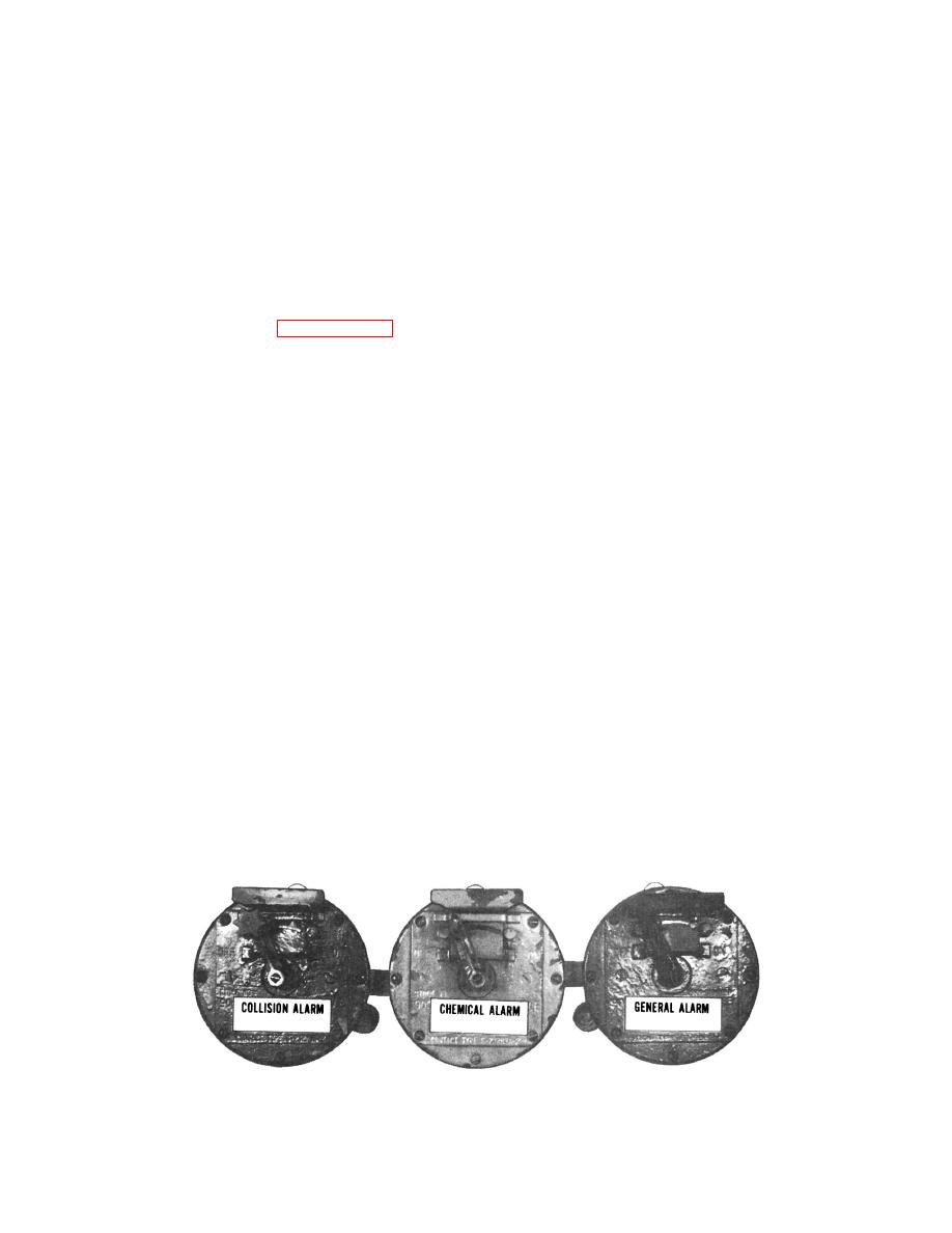
Figure 7-23.--Alarm contact maker arrangement. |
|
||
| ||||||||||
|
|
 systems aboard surface ships are capable of
Loudspeakers are usually provided with
generating and broadcasting collision alarms,
volume adjustments. The desired output level for
chemical attack alarms, and general alarms.
each loudspeaker will depend on where it is located.
Visual Alarm Indicators
Alarm Contact Makers
In areas where the noise level is high, such as
Alarm contact makers are installed at various
in engineering spaces and on hangar decks, visual
locations, such as the pilothouse/bridge and
alarm indicators are installed to alert personnel when
quarterdecks, where they are easily accessible to
an alarm is being sounded. The visual alarm
watch standers. The alarm contact makers are self-
indicators consist of lighting fixtures with red lamps
locking (in the OFF position), manual-release, lever-
installed in them. The red lamp lights steady when
operated switches. Operation of any alarm contact
the collision or chemical attack alarm is sounded and
maker will light both busy lights on all microphone
flashes when the general alarm is sounded.
control stations and transmit the alarm signal to all
1MC loudspeaker groups. Figure 7-23 is an
illustration of a typical alarm contact maker
OPERATIONAL SYSTEM TESTING
arrangement. The alarm contact makers are color
coded and prioritized according to their importance.
There are two methods for testing the system
The order of priority is controlled automatically by
for proper operation: (1) silent testing and (2) remote
relays in the control rack. The alarm contact makers
testing.
are color coded and prioritized as follows:
Silent Testing
1. Collision (green)
Since the system can operate on either
2. Chemical attack (yellow)
channel A or B and oscillator group 1 or 2, one
channel and one oscillator group can be on the line
3. General (red)
for ship's use while the other channel and group are
available for silent testing.
4. Unassigned A (gray)
To test channel A and oscillator group 1,
5. Flight deck crash (red)
proceed as follows:
If a low-priority alarm is being sounded and the
1. Place the LOAD DISC switch in the OFF
contact maker for a higher priority alarm is operated,
position.
the lower priority alarm will be silenced and the higher
priority alarm will be transmitted over the 1 MC
2. Place the AMPLIFIER CHANNEL
loudspeakers. Conversely, the operation of a low-priority
SELECTOR switch to the 1MC-B/6MC-B
alarm contact maker has no effect on a high-priority
position, and turn the OSCILLATOR
alarm that is being transmitted.
GROUP SELECTOR switch to the NO. 2
position. This puts channel B and
The nature and number of 1MC alarms
oscillator group 2 on the line, and leaves
installed aboard ship is dependent on the type and
channel A and oscillator group 1 available
mission of the ship. As a rule, however, all 1MC
for testing.
7.344
7-19
|
|
Privacy Statement - Press Release - Copyright Information. - Contact Us |
