 |
|||
|
Page Title:
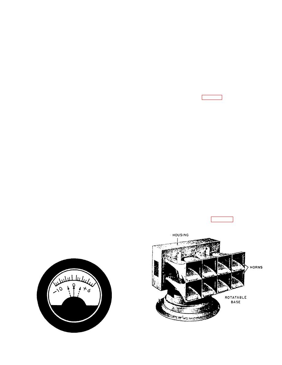
Figure 7-21.--Volume indicator meter. |
|
||
| ||||||||||
|
|
 and circuit 6MC are in use, (2) both circuit 1MC and
station. When an announcement is made from any
circuit 6MC are using the same amplifier channel, or
microphone control station, all loudspeakers selected at
(3) an alarm signal is being transmitted.
that station, except the loudspeaker in the immediate
area of the station, will receive the anouncement.
When both circuits are using the same
amplifier channel, circuit 1MC takes priority over
The loudspeakers associated with circuit 1MC
circuit 6MC. Therefore, if circuit 6MC is in use and a
are normally divided into four groups. These
circuit 1MC loudspeaker group is selected from
loudspeaker groups are designated (1) officers, (2)
another microphone control station and a
topside, (3) crew, and (4) engineering. There is only
transmission is initiated, circuit 6MC will be cut off.
one circuit 6MC loudspeaker group, with only one or
The announcement will then go out to the circuit
two loudspeakers installed.
1MC loudspeakers only.
After making an announcement over circuit
1MC, make sure you place the loudspeaker group
VOLUME INDICATOR METER.-- A
control switches selected in the OFF position. If any
volume indicator meter (fig. 7-21 ) is mounted on the
loudspeaker group control switch at any lMC
front of the microphone control station. This meter
microphone control station is left in the ON position,
indicates that the system is ready for use. his meter
announcements made from any other control station
also indicates the amount of output volume when a
will go out on those loudspeakers.
transmission is made. This meter is calibrated in
decibels from -10 dB through 0 dB to +6 dB. When
BUSY INDICATOR LIGHTS.-- Two busy
the press-to-talk switch on the microphone is
depressed, the meter needle should deflect. When an
indicator lights are mounted on the front of the
announcement is being transmitted, the meter needle
microphone control station, one for the 1MC (busy 1)
should deflect to 0 dB on peaks for normal volume.
and one for the 6MC (busy 2). These lights indicate if
the associated circuit is in use, thereby avoiding the
possiblity of initiating a call through that circuit.
Loudspeakers
Before making an announcement, make sure the
busy light for the desired circuit is not lighted.
Several different types of loudspeakers are
used with circuit 1 MC to suit different needs. In
Except in an emergency, do not attempt to
areas with comparatively low noise levels, such as
use circuit 1MC when the busy indicator light is
living spaces, low-power, radiator-type loudspeakers
lighted. If another microphone control station has
are used. On weather decks and in areas with high
already selected a circuit 1MC loudspeaker group(s)
noise levels, such as engineering spaces, high-power,
and is initiating an announcement, the transmission
folded-horn loudspeakers are used.
will go out to all loudspeakers selected at both
microphone control stations.
Circuit 6MC requires the use of a multiunit
straight-horn loudspeaker (fig. 7-22). This type of
When the circuit 6MC busy indicator light is
loudspeaker projects a narrow, powerful beam.
lighted, it will have no effect on circuit 1MC operation.
When both busy indicator lights are lighted,
three possible conditions exist: (1) both circuit 1MC
loudspeaker.
7-18
|
|
Privacy Statement - Press Release - Copyright Information. - Contact Us |
