 |
|||
|
|
|||
| ||||||||||
|
|
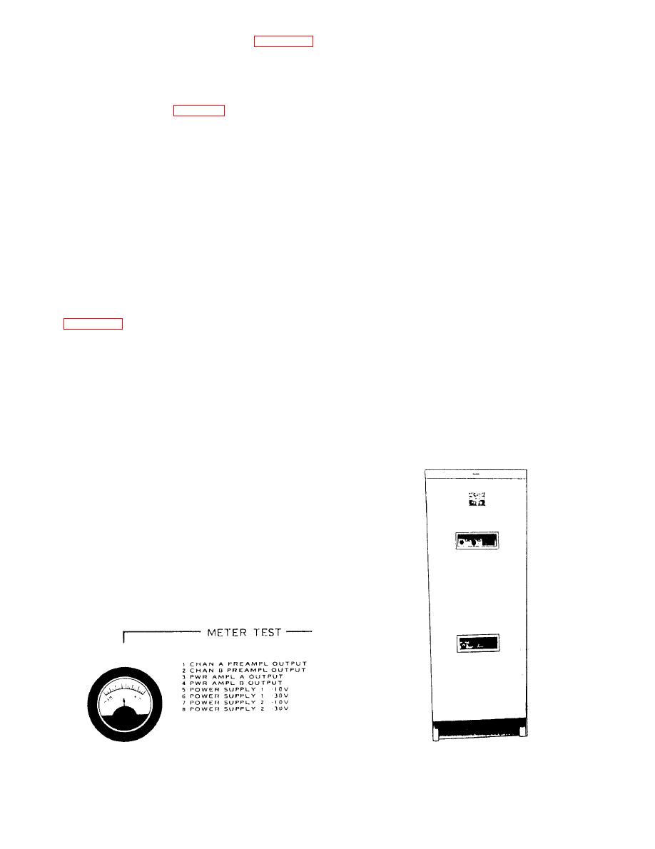 each amplifier. Normal operation of each stage will
amplifier channels and oscillator groups. Figure 7-17 is
an illustration of the test meter.
indicate a midscale reading (02 dB) on the meter.
Resistor R2101 is a potentiometer used to control
POWER RACK
the amplitude of the input signal being applied to V2103
and V2104. High-voltage switch S2101 is used to apply
The power rack (fig. 7-18) is a deck-mounted
plate power to the amplifier.
e n c l o s u r e that contains the two 500-watt,
audio-frequency power amplifiers and two ventilation
ADDITIONAL SOUND EQUIPMENT
blowers. The power switch for these blowers is located
on the control rack.
Additional sound equipment used with the system
The power amplifiers amplify the voice and alarm
includes (1) microphone control stations, (2)
signals received from their associated preamplifiers in
loudspeakers, (3) alarm contact makers, and (4) visual
the control rack and transmit the amplified signals back
alarm indicators.
to the control rack for further transmission to the
appropriate loudspeaker groups. The amplifiers
Microphone Control Stations
maintain a relatively constant output signal that is
independent of loudspeaker load. Therefore, impedance
The system has provisions for the connection of six
matching of the output is not critical, and adding or
type IC/MSB-2 microphone control stations. The
removing loudspeakers from the output of the amplifier
microphone control stations are installed at various
will have little or no noticeable effect on the output level.
locations aboard ship. The stations provide a means of
transmitting voice announcements over the 1MC or
6MC circuits and select the loudspeaker groups over
Each power amplifier consists of two separate
which the announcements will be broadcast. All stations
chassis. Chassis 1 contains all the tubes and parts
are capable of transmitting over circuit 1MC. Only
required for actual amplification of the audio signals.
station 1 is capable of transmitting over both circuit
This chassis consists of an amplifier stage, a
1MC and circuit 6MC. Station 1 is normally located in
phase-inverter stage, two driver-amplifier stages, and a
the pilothouse/bridge and has operational priority over
final power-amplifier stage. Two parallel-connected
the other five stations. The other stations are normally
tubes comprise each stage except the final stage, which
located at the quarterdecks.
has six tubes in a push-pull parallel circuit. This parallel
connection of twin-triode tubes permits normal circuit
operation despite failure or removal of one tube per
stage or two tubes in the final stage.
Chassis 2 contains all the parts required to furnish
plate power to chassis 1. This chassis consists of a
plate-power transformer, high-voltage rectifiers,
low-voltage rectifers, and a filament transformer.
There are two eight-position selector switches and
two meters mounted on the front of the power rack, one
for each amplifier. These are used to check the operation
of each stage of the amplifiers and the signal output of
7-16
|
|
Privacy Statement - Press Release - Copyright Information. - Contact Us |
