 |
|||
|
Page Title:
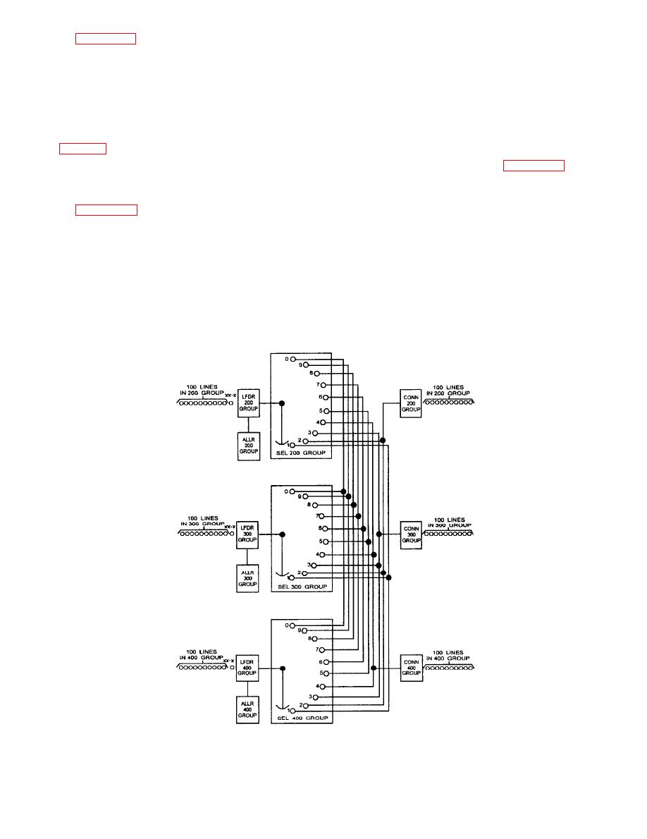
Figure 6-39.--The rotary switch in the selector, simplified block diagram. |
|
||
| ||||||||||
|
|
 --A calling station initiates finder action by
removing the handset from the cradle, causing shared
system, having 300 telephone stations in three groups
switching equipment to be placed under the control of
(switchboards) of 100 each. One finder/selector, one
the calling line by way of a connection in the wire
a l l o t t e r , and one connector represent each
bank.
switchboard. Each selector terminates into a connector
circuit. The selector (using a rotary switch) is the link
--Dialing from the calling station extends the
between the linefinder and the connector. Although
switching link to a wire bank position that terminates
the rotary switch has 20 positions, only 10 are shown
the audio leads of the called station.
The sample call diagramed in figure 6-40, view
B, is between station 262 (the calling party) and
Sample Call
station 474 (the called party). Assume that station 474
is not busy at the time of the call and that the idle
connector is connector No. 13 in the switchboard of
a sample call from one station to another. As an aid
the called station.
toward understanding the actions involved in
completing this call, keep in mind the following facts
The T and R leads for line 262 terminate in
concerning the MDM system:
switchboard cabinet No. 1 and extend to wire bank
position 62 by way of the line circuit serving level 6,
--Each telephone station has audio (tip and ring)
line 2. When the calling party operates the hook
leads that terminate in the wire bank of a switchboard
switch, line circuit 262 extends two sources of battery
cabinet.
|
|
Privacy Statement - Press Release - Copyright Information. - Contact Us |