 |
|||
|
Page Title:
Figure 6-30.--XY universal switch, schematic diagram. |
|
||
| ||||||||||
|
|
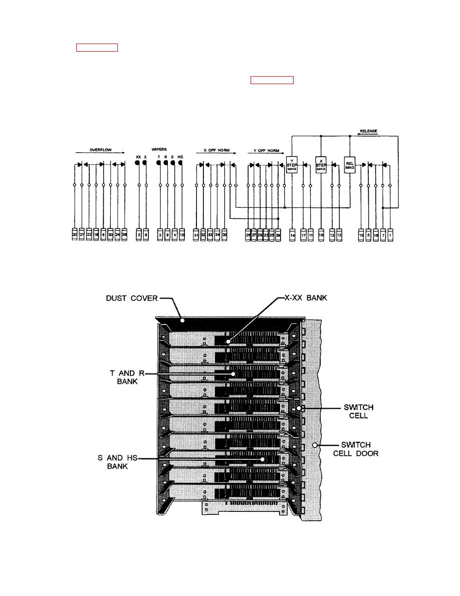 assemblies, and associated mechanical drive
magnet operates in a similar manner to drive the
wipers in the Y direction, which is into the wire bank.
hardware. A simplified schematic of the XY switch is
shown in figure 6-30. The switch steps first in the X
The overflow, X-off normal, and Y-off normal
direction controlled by a series of ground (positive)
spring pileups depend only on the position of the
pulses (periods of current flow) to the X-stepping
wipers for their operation. The spring position shown
magnet. Each time the magnet operates, the wipers
in figure 6-30 is the normal position. These springs
advance one step in the X direction. The Y-stepping
are used by the associated circuitry to perform various
6-36
|
|
Privacy Statement - Press Release - Copyright Information. - Contact Us |
