 |
|||
|
Page Title:
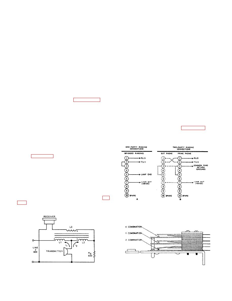
Figure 6-15.--Schematic diagram of the sidetone circuit. |
|
||
| ||||||||||
|
|
 receiver, you complete a dc circuit through the
Capacitor C1, varistor RV1, and resistor RB
switchboard, which operates relays to disconnect the
constitute an impedance balancing network for the
ringing generator and connect you to your calling
line impedance. Capacitor C1 also compensates for
party.
the line capacitance. Capacitor C2 prevents dc
voltages from being extended to the receiver.
Preventive Maintenance
Varistors RV1 and RV2 comprise a gain control
Preventive maintenance for the version 2 set is the
to maintain a constant input and output level
same as for the version 1 set.
regardless of whether the telephone is connected to a
long or a short loop. Resistor R1 is a current-limiting
Corrective Maintenance
device to protect varistor RV1 from high line-voltage
Corrective maintenance of the version 2 set
surges.
includes adjustments and replacement of failed
Varistor RV3 acts as a click suppressor and is
components.
almost a short circuit across the receiver when the
ADJUSTMENTS.-- There are four adjustments
voltage across RV3 reaches approximately 1 volt.
on the type G (version 2) telephone set: the hookswitch
This action also prevents demagnetization of the
contact springs adjustment, the ringer adjustment, the
receiver.
gong adjustment, and the dial illumination lamp inten-
sity adjustment. Dial illumination lamp intensity on the
simplified schematic diagram of the receiver sidetone
version 2 set is adjusted in the same manner as the
circuit. Because current will not flow through a
version 1 set. Dial speed on the version 2 set is not
balanced circuit, the turns ratio of inductors L1 and
adjustable; therefore, if the dial speed is too slow or too
L2 is unbalanced by a predetermined amount and the
fast, the dial must be replaced.
value of resistor RB is changed so as not to match the
line impedance. This way, a controlled amount of
an illustration of the hookswitch assembly. To adjust
signal can be induced into L3 to be used as receiver
sidetone.
R I N G E R CIRCUIT.-- The ringer can be
connected to the telephone line for one- or two-party
service. Figure 6-16, views A and B, illustrates how
the telephone set is connected for the service desired.
For two-party service, ringing is extended to the
prime telephone set over the R (L2) lead and to the
extension set over the T (L1) lead.
When a caller dials your number, the ringing
generator located in the automatic dial telephone
switchboard applies 75 to 100 volts ac at 20 Hz to the
ringer of your telephone set through capacitor C1 (fig.
|
|
Privacy Statement - Press Release - Copyright Information. - Contact Us |
