 |
|||
|
Page Title:
Figure 6-11.--Dial speed adjustment diagram. |
|
||
| ||||||||||
|
|
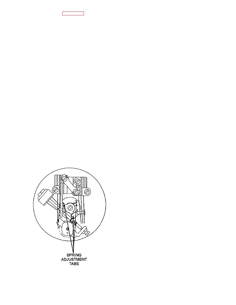 The following paragraphs will discuss the
dial frame as shown in figure 6-11. To increase dial
procedures for replacing the components of the type
speed, use a pair of needle-nosed pliers to detach the
G (version 1) telephone set.
tension spring hook from the tab being used. Then,
Handset Transmitter and Receiver Units.--
attach the tension spring hook to the next tab in the
The transmitter and receiver units are not repairable
clockwise direction. To decrease dial speed, attach the
and must be replaced if defective.
hook to the next tab in the counterclockwise direction.
To replace a transmitter unit, unscrew the
REPLACEMENT OF COMPONENTS.--
transmitter cap and lift the transmitter unit out of the
Most malfunctions of the type G (version 1) telephone
transmitter mounting cup. Insert the new transmitter
set will be reported by those using the set. After
unit in the mounting cup and screw the transmitter cap
verifying the malfunction, you should check all
onto the handset.
associated wiring for correct and secure connections
To replace a receiver unit, unscrew the receiver
before you attempt to troubleshoot the set for faulty
cap and lift the receiver unit out of the handset.
components.
Disconnect the handset cord red lead and green lead
from the screw terminals of the receiver unit. Connect
When working on the inside of the telephone set,
the red lead and green lead to the the screw terminals
you must follow high-voltage safety procedures.
of the new receiver unit. Insert the new receiver unit
System line voltages can be as high as 54 volts dc and
into the handset and screw the receiver cap onto the
ringing voltages as high as 110 volts and can be
handset.
dangerous. Always turn off and tag out the telephone
Handset Cords.-- Handset cords are standard
station line switch at the automatic telephone
stock items and can be readily replaced when the cord
switchboard before you begin working on the internal
becomes worn, frayed, or defective. To replace a
components of the telephone set.
handset cord, remove the telephone set from its
When replacing the type G modular telephone
enclosure and disconnect the three handset cord
sets, be sure you use the correct model set for the
terminal wires from the terminal board on the set.
enclosure concerned.
Remove the cord from the telephone set and the
handset from its holder. Remove the receiver unit from
the handset, and disconnect the cord terminal wires
from the receiver unit. Remove the transmitter unit
and the transmitter mounting cup. Disconnect the
handset cord terminal wires from the mounting cup.
Carefully pull the handset cord from the cord hole in
the handset housing.
Insert new cord terminal wires into the housing
cord hole. There is one long green wire and one red
jumper wire for connection to the receiver. There is
also one short red wire and one short yellow wire for
connection to the transmitter mounting cup. The other
end of the red jumper wire connects to the same
terminal on the mounting cup as the short red wire.
The cord is pressure-fitted in the handset housing and
locked in place by two tabs on the transmitter
mounting cup.
Connect the handset cord terminal wires to the
mounting cup, and put the transmitter back in the
handset. Connect the cord terminal wires to the
receiver, and put the receiver back in the handset.
Gently insert the handset cord through the cord hole
in the chassis of the telephone set. Install the strain
6-12
|
|
Privacy Statement - Press Release - Copyright Information. - Contact Us |
