 |
|||
|
Page Title:
Figure 5-13.--Sound-powered telephone head set-chestset transmitter circuit. |
|
||
| ||||||||||
|
|
 Sound-powered handsets are usually repaired on
location because they are permanently connected. When
trouble develops in a sound-powered headset-chestset,
the usual procedure is for the operator to bring it to the
IC shop and exchange it for a good one. This procedure
provides each station with properly operating sets at all
times. The IC shop should maintain a log of all sets
turned in; this will aid in locating faulty circuits or
identifying operators who continually abuse their sets.
PRECAUTIONS.-- When repairing sound-
powered telephones, you should observe the following
precautions:
Do not repair telephones on a dirty workbench.
transmitter circuit.
The magnets in the units may attract iron filings,
A short circuit in a single sound-powered
which are difficult to remove.
transmitter or receiver unit will render an entire circuit
Before disassembling a set, make a wiring
inoperative because all sound-powered telephones on
diagram showing the color coding, polarity, or
the circuit are connected in parallel. Operation of
terminal numbers of the lead connections.
Never alter the internal wiring of sets.
Always replace parts exactly as they were before
disassembly.
INSPECTION.-- You should make a routine in-
spection of sets before you begin to repair the sets to deter-
mine whether you should replace physically defective
parts. Many troubles may be located by inspecting the
set for damaged cord or insulation; cord pulled out of
units; loose units; defective or broken pushbuttons; and
broken or damaged parts, such as unit covers, neck strap,
chestplate, junction box, plug, and headband.
TRANSMITTER AND RECEIVER UNITS.--
Transmitter and receiver units are not repairable. If these
units become defective, they must be replaced. Both of
these items are standard stock items.
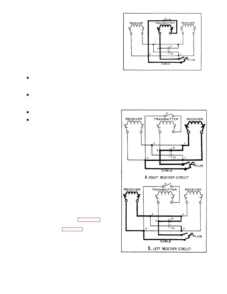
OPEN AND SHORT CIRCUITS.-- When testing
the units for open and short circuits, you should use a
low-voltage ohmmeter to avoid damage to the sound-
powered transmitter and receiving units. Continuity
tests may be made from the chestplate junction box on
sound-powered headset-chestsets. Figure 5-13 is an
illustration of the transmitter circuit of a sound-powered
telephone headset-chestset. Figure 5-14 is an illustration
of the receiver circuits. When testing the plug cable or
tinsel cords of a sound-powered headset-chestset, you
should disconnect them from the junction box. The
normal dc resistances of the sound-powered transmitter
and receiver units are 10 ohms and 62 ohms
respectively. If the plug cable and tinsel cords test out
recelver circuits.
satisfactorily, then you should check the capacitors.
5-15
|
|
Privacy Statement - Press Release - Copyright Information. - Contact Us |
