 |
|||
|
Page Title:
Figure 5-5.--Line cutout switches in the open and closed positions |
|
||
| ||||||||||
|
|
 All primary circuits are provided with a tie line
primary stations, the talker can easily reestablish
between their respective switchboard or switchbox for
communications with the control station by unplugging
cross-connection with their auxiliary circuits. The tie
the headset from the primary jackbox and plugging it
lines are fitted with a tie switch at one end and a tie +
into the auxiliary jackbox.
(tie plus) switch at the other end. The tie switch is
One disadvantage of paralleling circuits is
normally open and is closed only to parallel two circuits.
overloading transmitters. Each sound-powered
The tie + switch is normally closed and is opened only
telephone receiver unit consumes electrical energy
in the event of casualty, to disconnect the defective
when converting transmitted electrical signals to
circuit or tie line.
audible signals. As receiver units are added, the demand
for electrical energy may exceed the capability of the
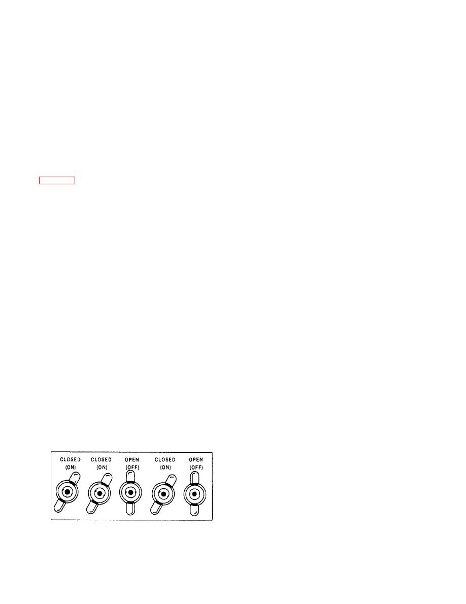
When the patch cord method of paralleling is used,
transmitter unit, resulting in the transmitter becoming
the following conditions may be obtained:
overloaded. An overload condition reduces the input
1. When the line cutout switches of both lines are
electrical energy available to each receiver unit, with a
open, the two lines will be connected together, but will
corresponding reduction in receiver output volume. The
not be tied in with any other station of either circuit.
reduced audio output may render the circuit ineffective.
The number of receivers it takes to overload a circuit
open and closed positions.
varies; therefore, the controlling station should be alert
to garbled messages or frequent requests for repeats,
2. When the line cutout switch of only one line is
indicating the circuit is overloaded.
closed, the two lines will be tied together and also
connected to the other stations on the circuit of which
A second disadvantage of paralleling circuits is that
the line cutout switch is closed.
as the number of stations on a circuit increases,
conversations may increase, resulting in confusion. This
3. When the line cutout switches of both lines are
can be remedied by all stations exercising good circuit
closed, all lines of the two circuits will be tied together.
discipline.
Thus, by manipulating patch cords and individual
Under normal operating conditions, circuits are
line cutout switches, you can connect any pair of lines
usually paralleled to reduce the number of talkers
together and any line to any circuit or combination of
required. As conditions of greater readiness are set,
circuits on the switchboard.
more talkers are assigned and fewer circuits are
C i r c u i t s connected to switches on the
paralleled. Few, if any, primary circuits are paralleled
communication consoles in the combat information
under the highest condition of readiness.
center (CIC) may also be paralleled by the console
operators. Since each circuit is routed to a number of
CASUALTY COMMUNICATIONS
plotter's positions, you must take care to avoid
Circuit X40J is designated the casualty
In an extensive sound-powered telephone system,
communication circuit. This supplementary string
circuit provides a means of rigging emergency
paralleling of circuits has both advantages and
disadvantages. One advantage is that it allows a
communication lines between vital stations after a
controlling station to extend supervision over several
casualty has occurred. This circuit applies to combatant
different stations, using fewer talkers. Another
ships and auxiliary ships, 200 feet and over in length,
fitted with weapons.
advantage is that if communications is lost to one of the
Permanent vertical riser cables are installed
between single telephone jackboxes located port and
s t a r b o a r d in vital below-deck stations and
corresponding four-gang jackboxes located port and
starboard on the first weather deck directly above each
below-deck station (hangar deck on aircraft carriers).
Each single jackbox installed in the below-deck
stations contains a nameplate that indicates the circuit
identification X40J. Below-deck stations include
positions.
steering gear rooms, engine rooms, emergency
|
|
Privacy Statement - Press Release - Copyright Information. - Contact Us |
