 |
|||
|
Page Title:
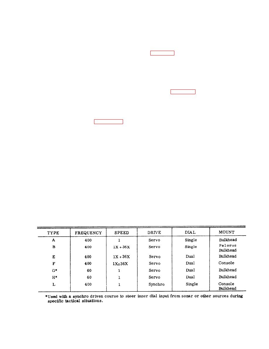
Figure 4-51.--Gyrocompass repeaters by letter designation. |
|
||
| ||||||||||
|
|
 An additional feature is the low noise and normal
WATCH STANDING
(nonlow) noise characteristic of several repeaters. In the
The AN/WSN-2 operates unattended after a mode
nonlow noise variety, the servo and dial assembly mount
of operation has been selected and the automatic
directly to the cast housing. In the low noise variety, the
mounting is on vibration isolators similar to rubber
alignment sequence is completed. Audible and visual
shock mounts.
extension alarms will alert watch standers at various
locations upon loss of normal power to the compass or
if a malfunction exists within the compass.
block and cord. The inner dial is single speed and the
blocked out outer dial is 36 speed. These repeaters are
SHIP'S COURSE INDICATORS
generally located in enclosed spaces, such as the OOD's
(REPEATERS)
repeater on the bridge.
The trend to transistorized equipment has resulted
The basic block diagrams of the various repeaters
in gyro installations being equipped with highly reliable
are shown in figure 4-53. View A shows the type L
transistorized ship's course indicators, or repeaters as
repeater synchro drive. View B displays the type A servo
they are commonly called. Ship's course indicators are
drive single speed. In view C, types B, E, and F are
used to visually display gyrocompass heading data for
depicted, and view D shows the G and H course-to-steer
navigational purposes. They are installed at the helm, on
repeaters.
the bridge wings, in the after steering room, and other
remote locations aboard ship. Figure 4-51 is a
The operation of the components is standard;
breakdown of the various types of ship's course
however, and explanation of the mixer and antistickoff
indicators used with gyrocompass systems.
voltage may be of assistance.
The several variations of mounting dials, data
The 36X synchro control transformer determines
transmission systems, and power requirements for
the accuracy of the indicator, but because this synchro
ship's course indicators will be discussed in the
has 36 null positions for one revolution of the indicator
following paragraphs.
dial, the 1X synchro sets the proper null. The two
Units may be designated as single-speed or 1 and
synchro rotors are connected in shunt through a mixing
36 speed. Single-speed units contain one synchro
network consisting of pairs of diodes and two resistors.
control transformer in larger units and one synchro
The mixing network performs three functions. First, it
receiver in miniature units. The 1 and 36 speed units
effectively opens the 1X synchro signal circuit
provide greater accuracy in reading and contain two
whenever the indicator dial is within 2.5 of null.
control transformers. In the 1 and 36 speed, coarse
Second, it limits or attenuates the 36X synchro signal
control is 1 speed and fine control is 36 speed.
whenever the 36X synchro is more then 2.5 from its
null. Third, it keeps synchro loading to its minimum
Units also may be divided by power requirements
with some using 60 Hz and others using 400 Hz.
allowable level.
|
|
Privacy Statement - Press Release - Copyright Information. - Contact Us |
